OPERATION
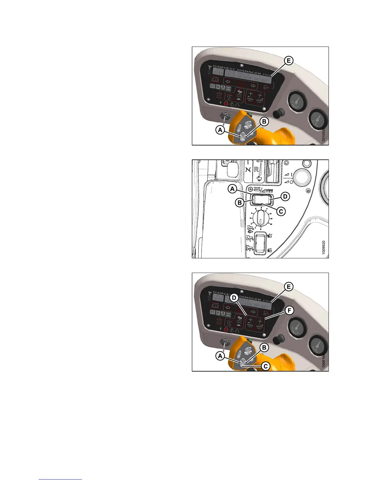
2. Using HEADER TILT SWITCHES (A) and (B) on the
ground speed lever (GSL), set center-link to mid-range
position (05.0 on Display [E]).
Figure 4.292: Operator Console
3. Select a d e ck position with D ECK SHIFT switch (A)
from one of the following delivery options:
• B - Left side delivery
• C - Center delivery
• D - Right side delivery
Figure 4.293: D eck S hift Switch
4. Using HEADER DOWN switch (A) on the GS L, lower
header fully with lift cylinde rs fully retracted.
5. Using LEFT FLOAT SWITCH (B), push + to increase
float or – to decrease float on left side of header.
Display (D) will indicate selected float value for left
side, for example (8.0 L FLOAT R ##.#).
6. Repea t for right side float w ith RIGHT switch (C).
Display (D) will ind ica te float value for both sides, for
example (8.0 L FLOAT R 3.0).
Figure 4.294: Operator Console
147649 292 Revision A