Installation and Commissioning
GARD 8000 SYS RFL Electronics
November 28, 2017 4-60 973.334.3100
If the testing is performed in ‘Point-to-Point’ Two-Terminal setup, verify the Current Diff
Relay Comms status using the above steps without enabling a Local loopback at the Local
and Remote End.
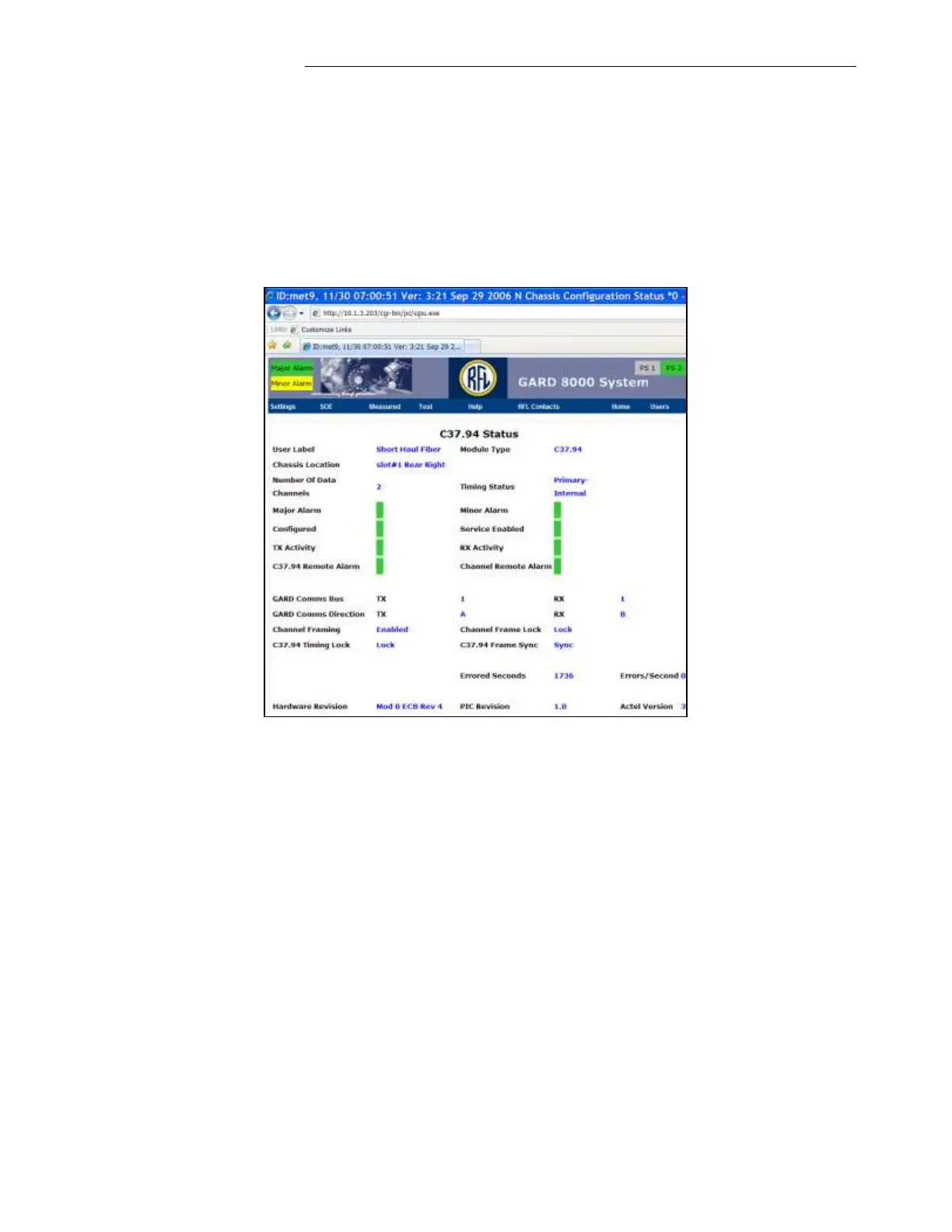
The status of the Communications channel can also be verified on the Comms interface
programmed to transport the Current Diff channel. From the ‘Home’ page click on the
Comms interface used for the Current Diff and verify the status of the communication
channel (See below). A Minor Alarm will be active for the duration of the Forced Local
Loopback.
4.6.4.9 INPUT/OUTPUT MAPPING VERIFICATION:
The physical Inputs and Outputs for the Current Diff Relay are mapped on the System Logic
Configuration web page. Any available hardware input or output can be freely assigned to any
logical input or output that is available in the Input or Output mapping block (use the GARD
8000 logic drawings as a reference).
Verify which logical inputs and outputs of the Current Diff Relay are mapped to the hardware
inputs and outputs using the web pages. Additional logical inputs or outputs could be mapped
in the Input Mapping and Output Mapping Logic blocks located in the Current Diff Relay
Logic Design.


 To Next Page