Installation and Commissioning
GARD 8000 SYS RFL Electronics
November 28, 2017 4-61 973.334.3100
4.6.4.10 LED ASSIGNMENT VERIFICATION:
Verify the front panel LED assignment used for the Current Differential Relay. The front panel
LED’s can be custom programmed to display various GARD System or Current Diff Relay
functions or conditions. Please refer to the GARD 8000 Logic drawing or GARD 8000
webpage (Settings > System Labels and Triggers > LED Logic Assignments).
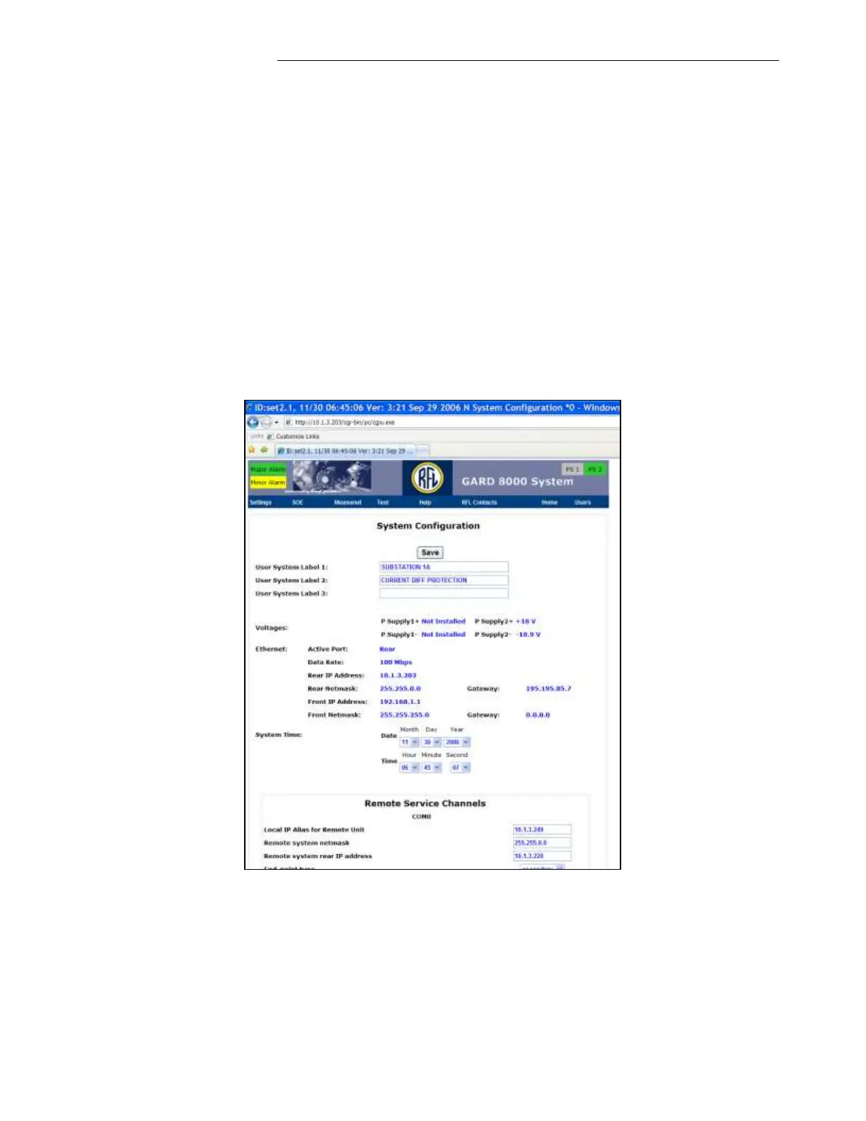
4.6.4.11 SYSTEM CONFIGURATION VERIFICATION
1. From the ‘Home’ page click on the “Controller” module.
2. Verify ‘System Labels,’ Active Power Supply or Supplies Voltages, Rear Port IP Address,
Network Mask, and System Time and Date (the IRIG-B if connected will overwrite the System
Time and Date settings).
3. Modify the programmable settings, if needed.
If the remote station doesn’t have an Ethernet connection this page can be used to set up a 64Kbps or
8Kbps Remote Service channel (depending on the type of communication link). The Remote Service
Channel function of the GARD 8000 can be used to interrogate a remote end. Please refer to the
GARD8000 instruction manual (Section 2.13 and 5.3.4) for more information.


 To Next Page