Installation and Commissioning
GARD 8000 SYS RFL Electronics
November 28, 2017 4-74 973.334.3100
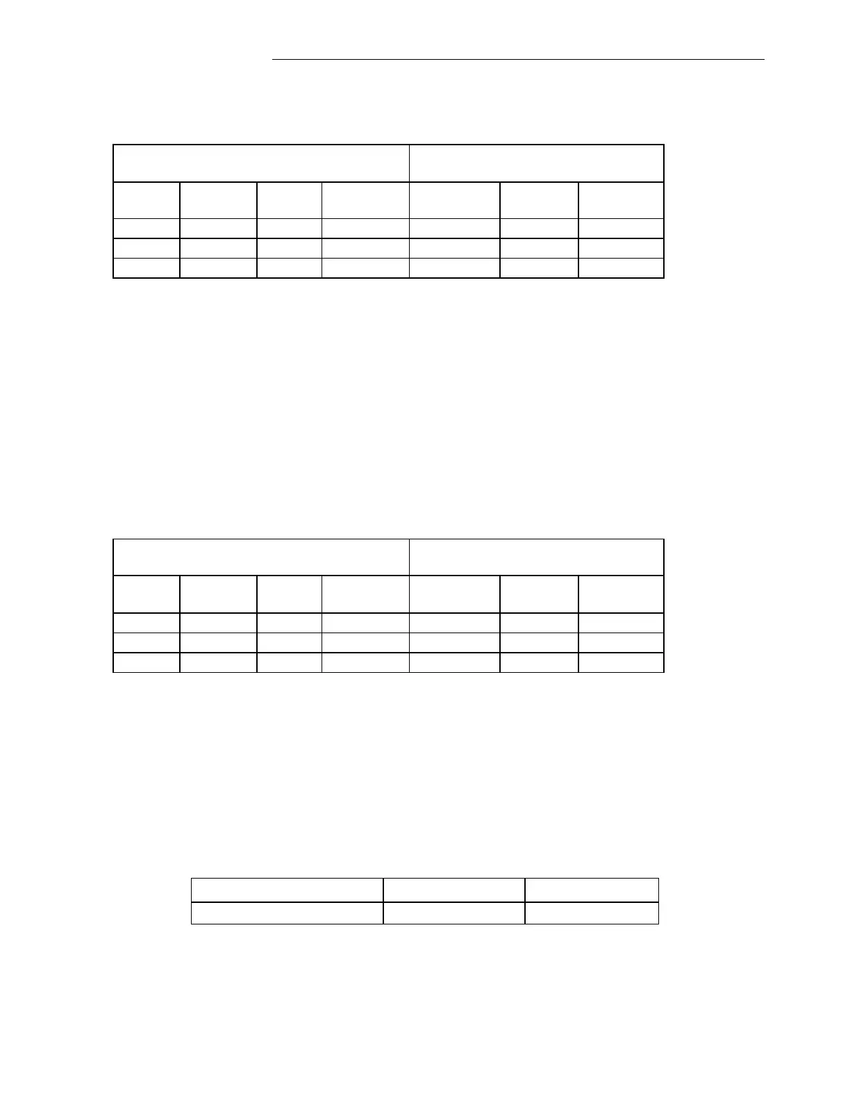
Phase to Ground Fault A G: Settings for a Remote End
Simulating External Trips using the provided test plans should not produce a Trip Condition!
4.6.4.16 TESTING BACK-UP OVERCURRENT FUNCTION:
1. Break the Communication Link.
2. Enable the ‘Back-up’ Setting on the webpage for ‘Current Differential Relay Backup
Settings.’
3. Enable ‘Overcurrent Backup.’
4. Program the Phase, Ground, and Timer Overcurrent settings as per the recommended Current
Differential Backup factory settings.
5. Setup a Power System Simulator for ‘Phase A’ to Ground Trips as shown below.
6. Run the test.
7. The Current Differential Relay should restrain and not trip since the ‘Phase A’ amplitude is
simulated at 5A and the Overcurrent Backup Phase setting in the GARD is programmed for
8A.
8. Change ‘Phase A’ amplitude to 10A.
9. Run the test again.
10. The Current Diff relay should trip for ‘Phase A’ to Ground fault.
11. Typical Trip Times for this test are shown below.
After each test, the operation of the trip outputs can be verified by retrieving the Current Diff
Relay SOE Records, System SOE records, Current Diff Relay Oscillography records, and
Current Diff Relay Last Trip.


 To Next Page