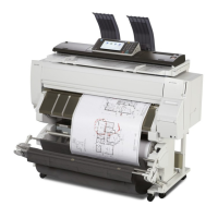
12. Connect the FFCs to the right connectors of the HRB. ( x2)
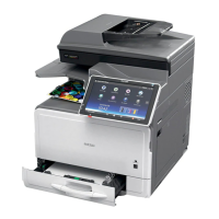
13. Attach the thermistor to the head tanks (Y1/M1) of the print head units.
• Insert the thermistor into the hole of the head tank from right to left, fold back the tip of the
harness [A], then feed the thermistor back into the hole.
• Insert the sensor head so that it placed above the harness in the hole of the head tank.
14. Place the ink tubes on the path of the print head, from right to left in order of Y1, M1, C,
Y2, and M2.
• Place the ink tube (Y1) on the path of the print head first. [A]
• Then place the ink tube (M1) upon the ink tube (Y1) on the path of the print head. [B]
• Then place the ink tube (C) upon the ink tube (M1) [C] and the ink tube (Y2) upon the ink tube
(C) on the path of the print head. [D]
4. Replacement and Adjustment
460