2-36 Xerox Internal Use Only Phaser 6500/WorkCentre 6505 Service Manual
Theory of Operation
Drive
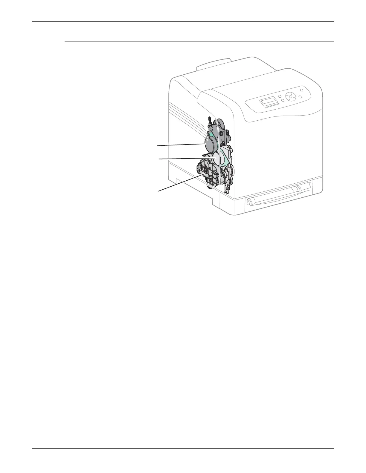
The drive for both the SFP and MFP consists of three assemblies:
• Main Drive Assembly — Drives the Imaging Unit, Transfer Belt, Registration
Rollers, and Feeder.
• Sub Drive Assembly — Supplies drive to the Fuser and Cyan, Magenta, and
Yellow developers in the Imaging Unit.
• Feed Drive Assembly — Transmits the driving force from the Main and Sub
Drive Assemblies to relevant parts. The drive path is changed by the Color
Mode Switching Solenoid located on the Feed Drive Assy. To change modes,
the solenoid activates, allowing Gear C to engage and rotate Cam C 180
degrees. In Black and White Mode, Cam C displaces Flange D3 to disengage
the sections of Gear D3. This prevents rotation of the CMY developers,
allowing only the Black Developer to rotate. The Color Mode Switching Sensor
detects the presence or absence of the flag on Cam C to report whether the
drive path is set for color (flag present) or black and white (flag absent).
s6500-053
Sub Drive
Main Drive
Feed Drive
http://www.manuals4you.com

 Loading...