Phaser 6500/WorkCentre 6505 Service Manual Xerox Internal Use Only 8-51
Service Parts Disassembly
SFP Upper Frame Assembly
While this procedure is not directly related to a specific part, upper frame removal
is necessary for servicing the HVPS or components of the Feeder Assembly. As few
parts as possible are removed to separate the assemblies.
1. Perform the service preparation steps on page 8-3.
2. Open the Front Cover.
3. Remove the Top Cover (page 8-15).
4. Remove the Right Side Cover (page 8-17).
5. Remove the Left Side Cover (page 8-18).
6. Remove the Rear Tray Cover (page 8-19).
7. Remove the Rear Cover (page 8-20).
8. Raise the Transfer Belt and latch in the upright position.
9. Remove the Drive Clutch and Bearing Kit (page 8-48).
10. Remove the Fan (page 8-119).
11. Remove the IP Board Cage (page 8-140).
12. Remove the Transfer Belt (page 8-112).
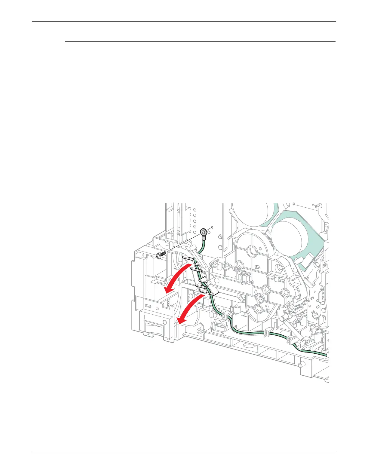
13. Remove the screw (silver, 6mm) that secures the Front Cover ground harness
to the printer. Do not remove the wire from the guides.

 Loading...