Creating the Split-Line
Next you will use the Flange surface to create the small split-line feature at
the center line.
The Flange surface can only be built from a surface edge, not a curve. This is
because it measures its angle from the surface edge, not from a draft direction.
So first, you will template your curves to make it easier to select the surface
edges.
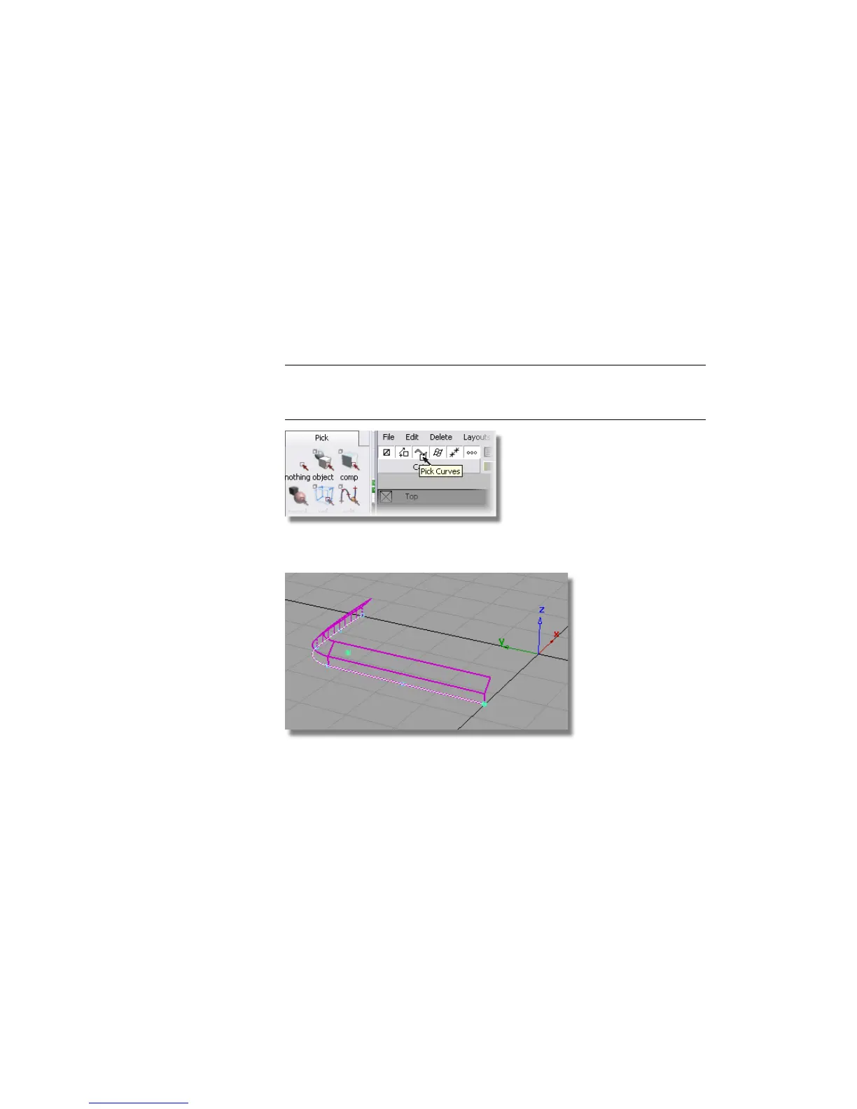
1 Choose Pick > Component and modify the options so that only curves
will be selected.
2 TIP You can either double-click the Pick > Component icon to set up the
options in the option window, or you can use the small icons in the menu
bar, as shown below.
3 Drag a pick box across the model. Only the curves are selected.
4 Choose ObjectDisplay > Template to turn the curves into a template that
will not be selected by the Pick > Object tool.
Now you will create some small Flange surfaces to represent the split-line
detail.
Part 2: Creating the Side Surfaces | 421