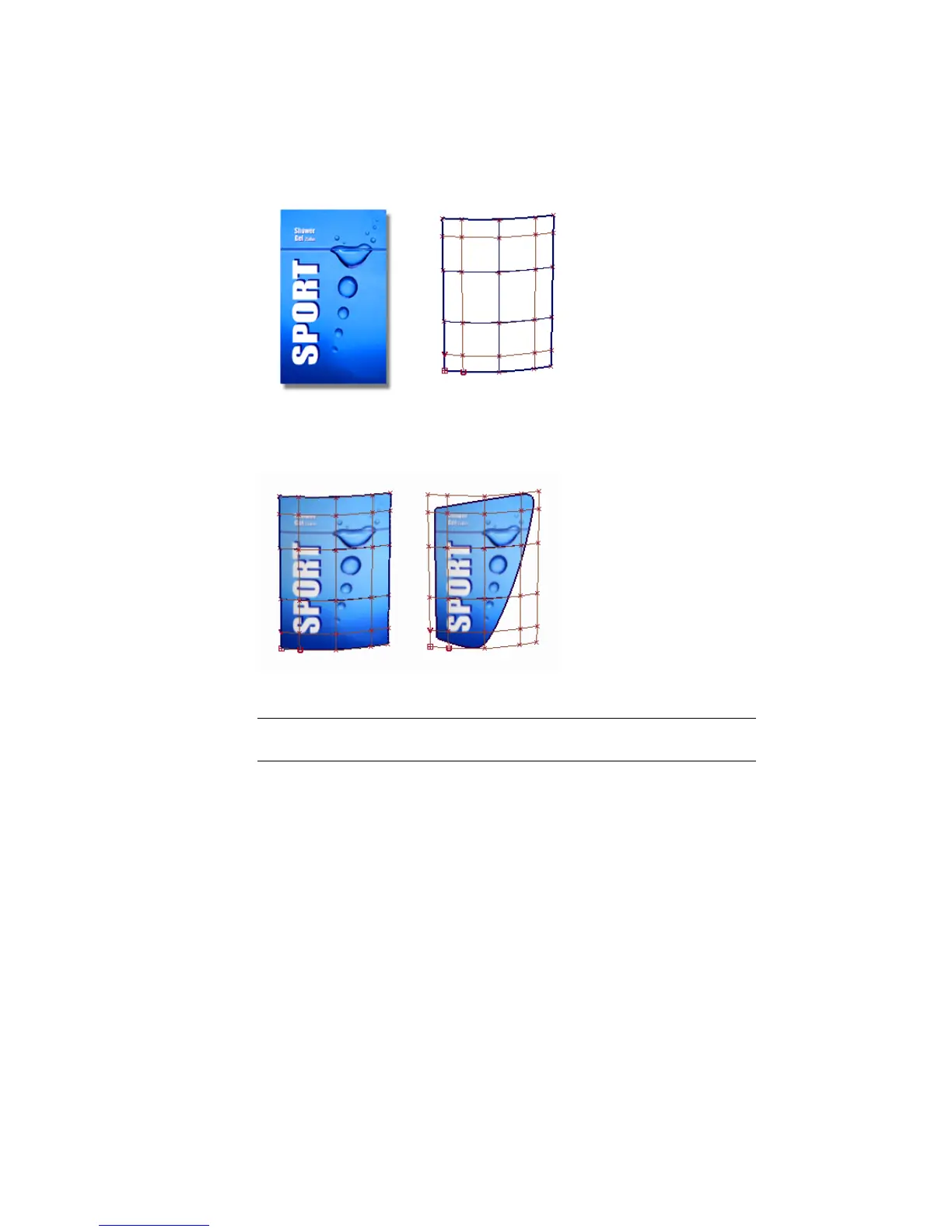
The result is that the graphic file follows the U and V directions of the surface.
If the surface is trimmed, the graphic appears on the part of the surface that
is visible.
To apply the graphic as a colored label, you will map the Color parameter.
TIP Mapping can be used on many of the shader parameters, such as transparency,
bump, or reflection.
Opening the tutorial file (optional)
If you successfully completed Part 1, proceed to the next step: Create a Label
Shader, below.
If you were not successful in part 1, open the file called
Render_Basics_part2.wire, located in the wire directory of the CourseWare
project. This file contains the completed model from Part 1.
648 | Chapter 10 Shaders and Lights