Monitoring
216
Instructions for use Zeus Infinity Empowered SW 2.n
ST screen display (optional)
In the display of the advanced ST option, all availa-
ble leads are displayed.
Measuring points
The start point and end point of the QRS complex
are determined automatically.
For a reliable measurement of the ST deviations,
the position of the ST Iso point and ST meas.
point on the display (B) can be adjusted.
Setting measuring positions:
z Touch the respective button. Use the rotary
knob to put the cursor on the required place and
confirm.
The following settings are possible:
C ST iso point: Setting the measuring position for
the isoelectric point
D ST meas. point: Setting the measuring position
for the ST measuring point
E ST trend scale: Amplitude setting for the ST
trends
F ST event duration: Setting the time after which
there will be an alarm if there has been an unin-
terrupted limit transgression
G ST monitoring: Switching the ST segment
analysis On/Off
H Save reference
I ST view, opens ST view in the Trends/Data di-
alog window
J The button opens the Alarms >All limits >
Hemodyn. dialog window for alarm limit setting
of the measured values ST LAT, ST INF,
ST ANT.
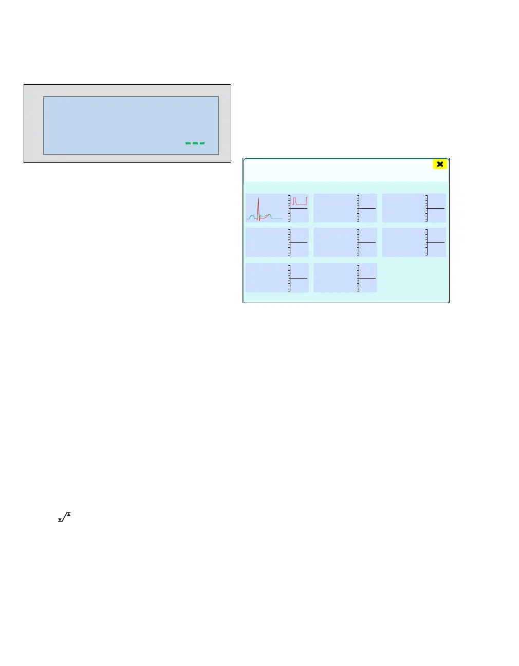
Display of hemodynamic data, ST analysis, ad-
vanced ST analysis (optional)
z Touch the ST view button (I).
Or
z In the Trends/Data > Hemodyn. dialog win-
dow, touch the ST view button, see page 184.
The example for the ECG lead II shows the display
of the current QRS complexes (green) and the one-
time measurement of the reference complexes
(red) above each other. In addition, a short time
trend of 30 minutes of the ascertained ST rise/fall is
applied.
223
0.1 0.1 0.1
0.1
0.1 0.1
0.1
ST
mm
III
III
aVL
aVR
aVF
V
V+
459
8
-8
ST view
inferior lateral anterior
30 min
II