Instructions for use Zeus Infinity Empowered SW 2.n 229
Monitoring
IBP screen display
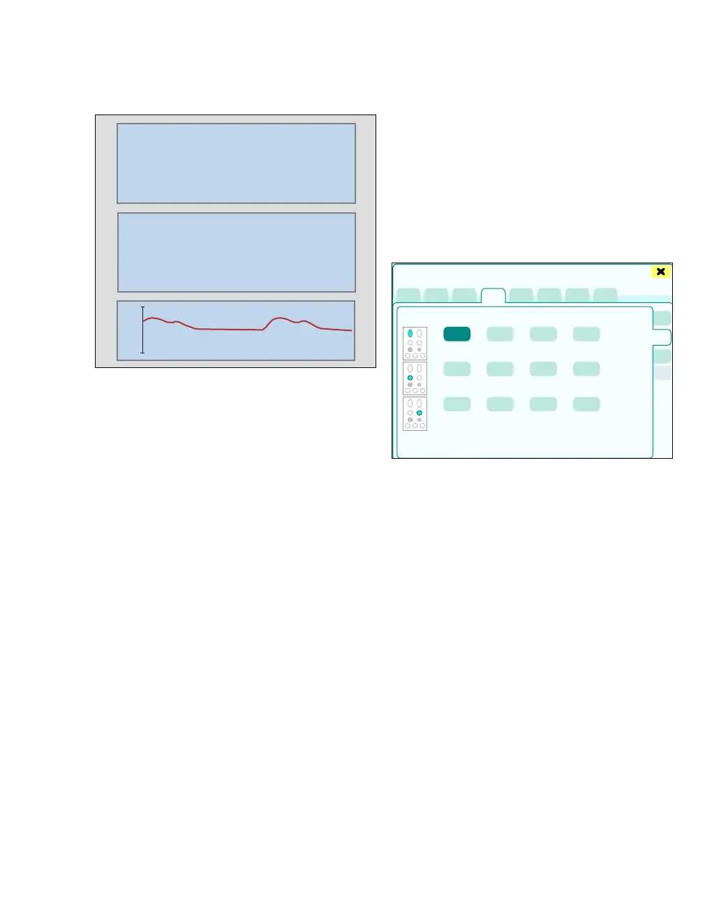
The display in the IBP parameter box depends on
whether a pulsating or a non-pulsating pressure is
being monitored. Parameter boxes in which pulsat-
ing pressure parameters are shown (ART, LV, PA,
RV, GP1, GP2) indicate systolic, diastolic and
mean pressure values. The illustration shows a typ-
ical parameter box of a pulsating pressure.
Parameter boxes for non-pulsating pressure pa-
rameters (LA, RA, CVP, ICP) only show the mean
pressure value.
IBP curves can be represented individually or over-
laid. In the overlaid representation, each pressure
curve can have its own scaling.
The following pressure parameters are perma-
nently assigned to the four curves: ART, CVP, PA,
and RA.
Additionally after touching the Display all button
(prerequisite: Display all button has been config-
ured, see page 332):
– Currently set alarm limits
Catheter positions
The pressure designation and catheter position de-
termine how the pressure signal is processed and
transferred to Zeus IE.
Date and time for the last zero adjustment and last
calibration as well as the calibration constant con-
cern the specific pressure processing channel and
remain for this channel even if there is a change in
catheter position or pressure designation.
In the Sensors/Parameters > IBP > IBP sites/
Channels dialog window, up to twelve IBP sources
are displayed in a matrix of 3 x 4 (up to 10 sources
can be measured simultaneously).
The signals are displayed in rows 1 to 3:
– Row 1: Data from the HemoMed Pod or the Y-
cable
– Rows 2 and 3: Data from Hemo2 or Hemo4
which are recorded via the Aux./Hemo 2/3
pressure connections on Zeus IE
Pressure parameters can be given a designation at
any time. If a parameter is designated without con-
nected accessories, then the following possibilities
arise:
– With direct connection of the pressure trans-
ducer cable, the adjusted measuring points are
used.
220
167/69
160
90
200
0
(106)
18
25
5
ART
mmHg
S
CVP
mmHg
ART
394
Sensors/Parameters