MPC5553/MPC5554 Microcontroller Reference Manual, Rev. 5
4-4 Freescale Semiconductor
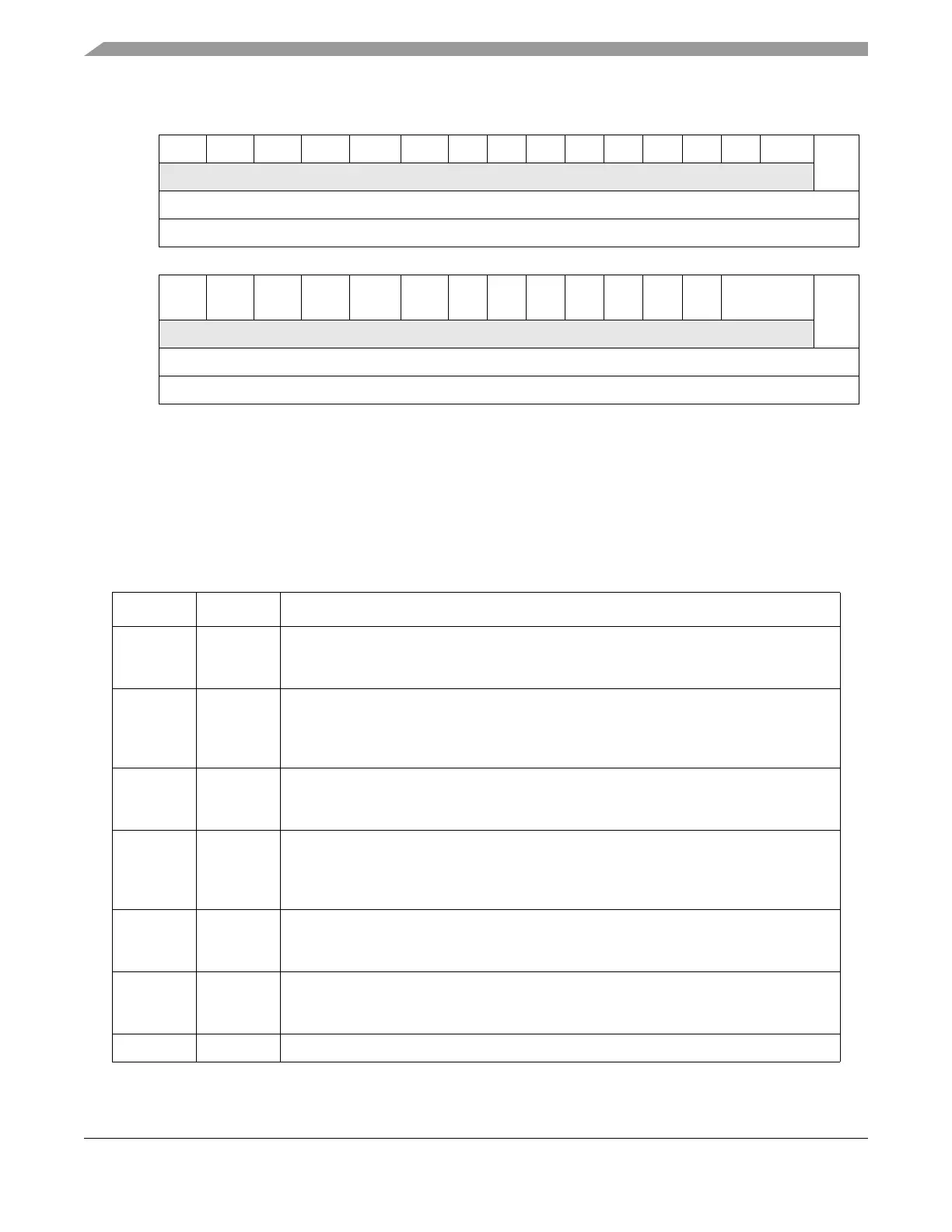
0 1 2 3 4 5 6 7 8 9 10 11 12 13 14 15
RPORSERSLLRSLCRSWDRSCRS00000000SSRSSERF
W
Reset
1
1 0 0 0 0 0 00000000 0 0
Reg Addr Base + 0xC
16 17 18 19 20 21 22 23 24 25 26 27 28 29 30 31
RWKP
CFG
0 0 0 0 0 0000000BOOTCFGRGF
W
Reset —
2
0 0 0 0 0 0000000 —
3
0
Reg Addr Base + 0x000C
1
The RESET values for this register are defined for power-on reset only.
2
The RESET value of this bit or field is determined by the value latched on the associated pin or pins at the
negation of the last reset.
3
The RESET value of this bit or field is determined by the value latched on the associated pin or pins at the
negation of the last reset. BOOTCFG can also be loaded with a default instead of what is on the associated pin
or pins.
Figure 4-1. Reset Status Register (SIU_RSR)
Table 4-2. SIU_RSR Field Descriptions
Bits Name Description
0 PORS Power-on reset status
0 No power-on reset has occurred.
1 A power-on reset has occurred.
1 ERS External reset status
0 No external reset has occurred.
1 An external reset has occurred.
The ERS bit is also set during a POR event.
2 LLRS Loss-of-lock reset status
0 No loss-of-lock reset has occurred.
1 A loss-of-lock reset has occurred.
3 LCRS Loss-of-clock reset status
0 No loss-of-clock reset has occurred.
1 A loss-of-clock reset has occurred due to a loss of the reference or failure of the
FMPLL.
4 WDRS Watchdog timer/debug reset status
0 No watchdog timer or debug reset has occurred.
1 A watchdog timer or debug reset has occurred.
5 CRS Checkstop reset status
0 No enabled checkstop reset has occurred.
1 An enabled checkstop reset has occurred.
6–13 — Reserved.