MPC5553/MPC5554 Microcontroller Reference Manual, Rev. 5
4-6 Freescale Semiconductor
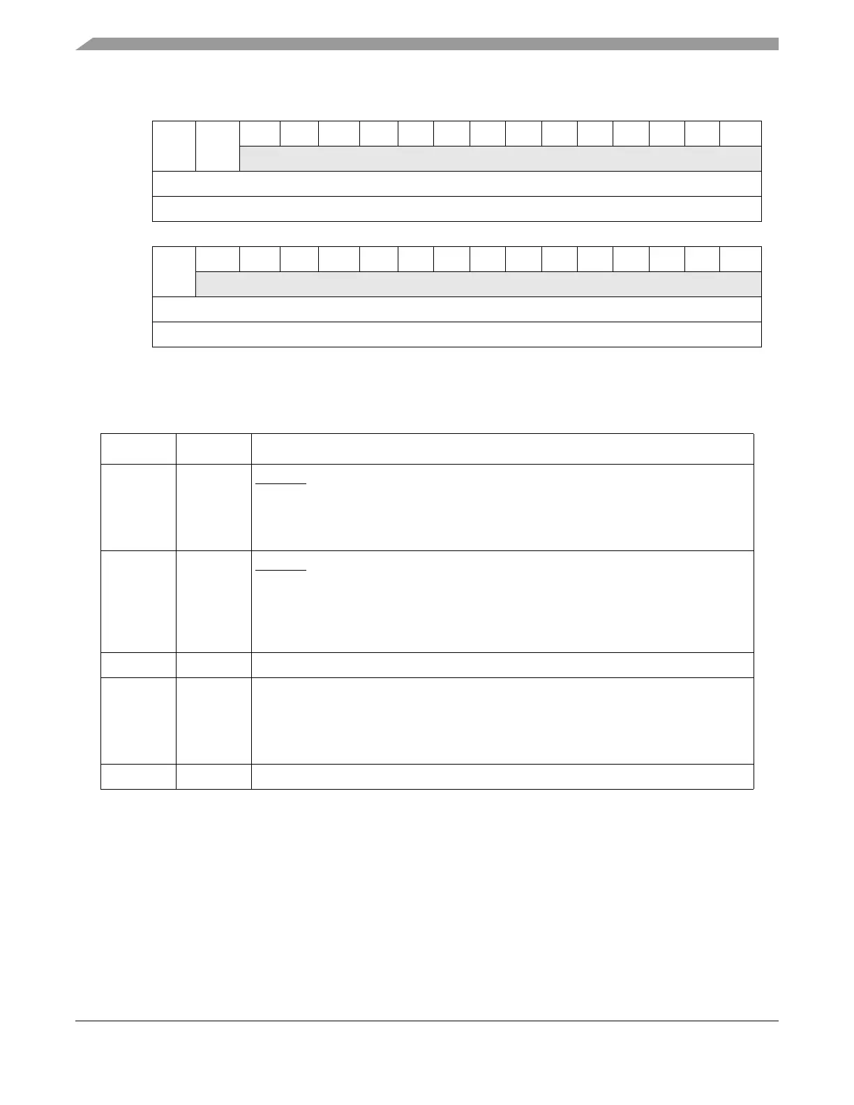
0 1 2 3 4 56789101112131415
RSSRSER0 0 0 0000000000 0
W
Reset
1
0 0 0 0 0 0000000000 0
Reg Addr Base + 0x10
16 17 18 19 20 21 22 23 24 25 26 27 28 29 30 31
RCRE0 0 0 0 0000000000 0
W
Reset 1
1
0 0 0 0 0000000000 0
Reg Addr Base + 0x0010
1
The CRE bit is reset to 1 by POR. Other resets sources do not reset the bit value.
Figure 4-2. System Reset Control Register (SIU_SRCR)
Table 4-3. SIU_SRCR Field Descriptions
Bits Name Description
0 SSR Software system reset. Writing a 1 to this bit causes an internal reset and assertion of the
RSTOUT
pin. The bit is automatically cleared by all reset sources except the software
external reset.
0 Do not generate a software system reset.
1 Generate a software system reset.
1 SER Software external reset. Writing a 1 to this bit causes an software external reset. The
RSTOUT
pin is asserted for a predetermined number of clock cycles (See Section 4.2.2,
“Reset Output (RSTOUT)”), but the MCU is not reset. The bit is automatically cleared when
the software external reset completes.
0 Do not generate an software external reset.
1 Generate an software external reset.
2–15 — Reserved.
16 CRE Checkstop reset enable
Writing a 1 to this bit enables a checkstop reset when the e200z6 core enters a checkstop
state. The CRE bit defaults to checkstop reset enabled. This bit is reset at POR.
0 No reset occurs when the e200z6 core enters a checkstop state.
1 A reset occurs when the e200z6 core enters a checkstop state.
17–31 — Reserved.