System Interface Unit (SIU)
MPC5553/MPC5554 Microcontroller Reference Manual, Rev. 5
Freescale Semiconductor 6-45
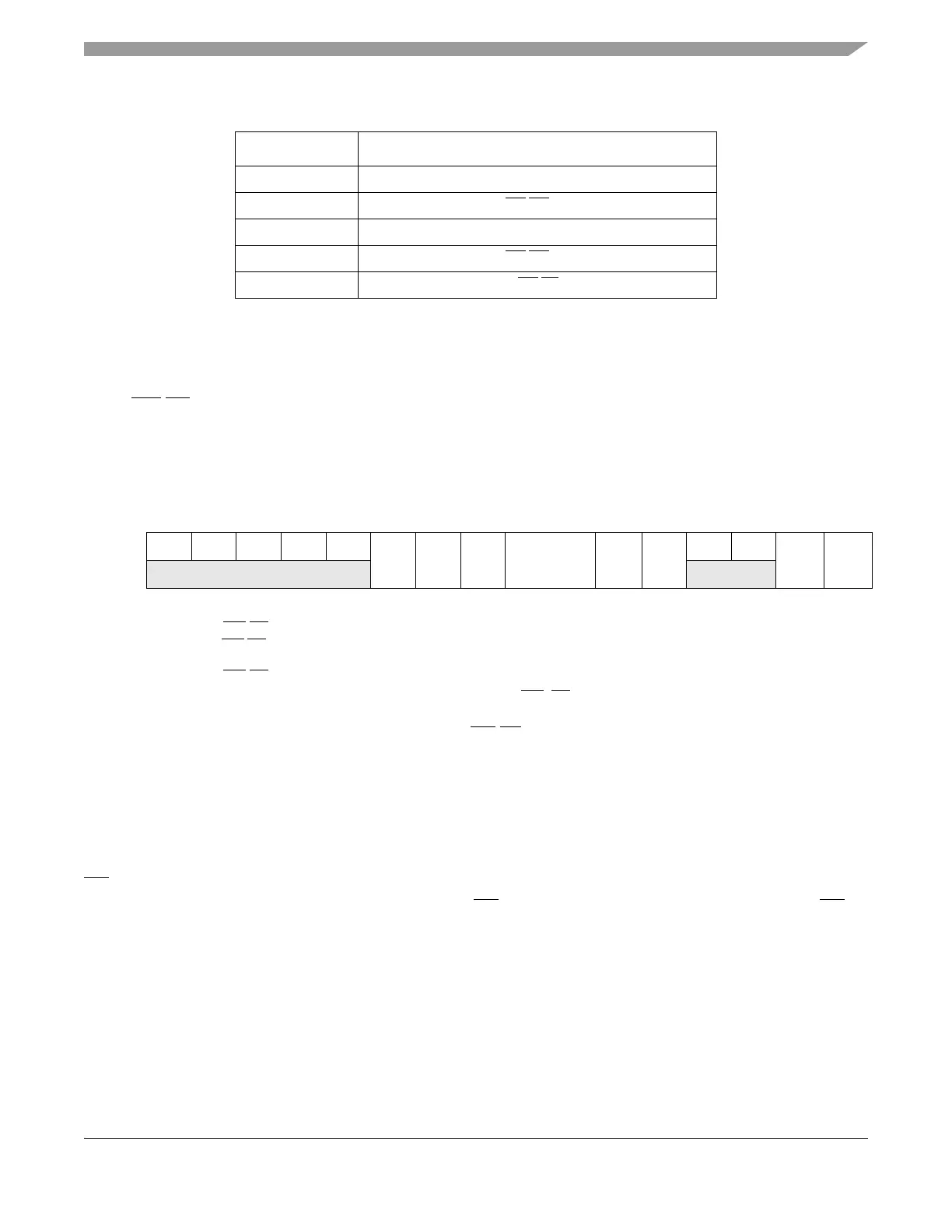
6.3.1.12.27 MPC5554: Pad Configuration Registers 64–67 (SIU_PCR64–SIU_PCR67)
The SIU_PCR64–SIU_PCR67 registers control the pin function, direction, and static electrical attributes
of the WE/BE[0:3]_GPIO[64:67] pins. The PA bit in the PCR64–67 registers selects between the write
enable/byte enable and GPIO functions. Set the WEBS bit in the EBI base registers to select between the
write enable or byte enable function.
Figure 6-40. MPC5554: WE/BE[0:3]_GPIO[64:67]
Pad Configuration Registers (SIU_PCR64–SIU_PCR67)
Refer to Table 6-16 for bit field definitions.
6.3.1.12.28 Pad Configuration Register 68 (SIU_PCR68)
The SIU_PCR68 register controls the pin function, direction, and static electrical attributes of the
OE_GPIO[68] pin. Because the MPC5553 calibration bus interface (CBI) and external bus interface (EBI)
share the same physical bus, the MPC5553 uses the OE
signal for the CBI as well as the EBI. The OE
function is not available in the 208 MAP BGA package. The GPIO function is the only signal available on
this pin in the 208 package.
Table 6-35. MPC5553: PCR66–PCR77 PA Field Definition
PA Field Pin Function
0b000 GPIO[66:67]
0b001 WE
/BE[2:3]
0b010 Reserved
0b011 WE
/BE[2:3]
0b100 CAL_WE
/BE[0:1]
1
1
For calibration only.
Address: Base + 0x00C0 through Base + 0x00C6 Access: Read / write[5:11, 14:15]
0123456789101112131415
R 00000
PA OBE
1
1
When configured as WE/BE[0:3], the OBE bit has no effect. When configured as GPO, set the OBE bit to 1.
IBE
2
2
When configured as WE/BE[0:3] or GPO, set the IBE bit to 1 to reflect the pin state in the corresponding GPDI register. Clearing
the IBE bit to 0 reduces power consumption. When configured as GPI, set the IBE bit to 1.
DSC ODE
3
3
When configured as WE/BE[0:3], clear the ODE bit to 0.
HYS
00
WPE
4
4
Refer to the EBI section for weak pullup settings when configured as WE/ BE[0:3].
WPS
4
W
RESET: 000000001100001 1