System Interface Unit (SIU)
MPC5553/MPC5554 Microcontroller Reference Manual, Rev. 5
6-94 Freescale Semiconductor
When an eQADC trigger is connected, the timer output is connected to the eQADC CFIFO trigger input.
To trigger the eQADC, the eTPU output must change to a state the eQADC recognizes as a trigger. Because
there are rising- or falling-edges, and low- or high-gated trigger types, it is possible to trigger the eQADC
immediately.
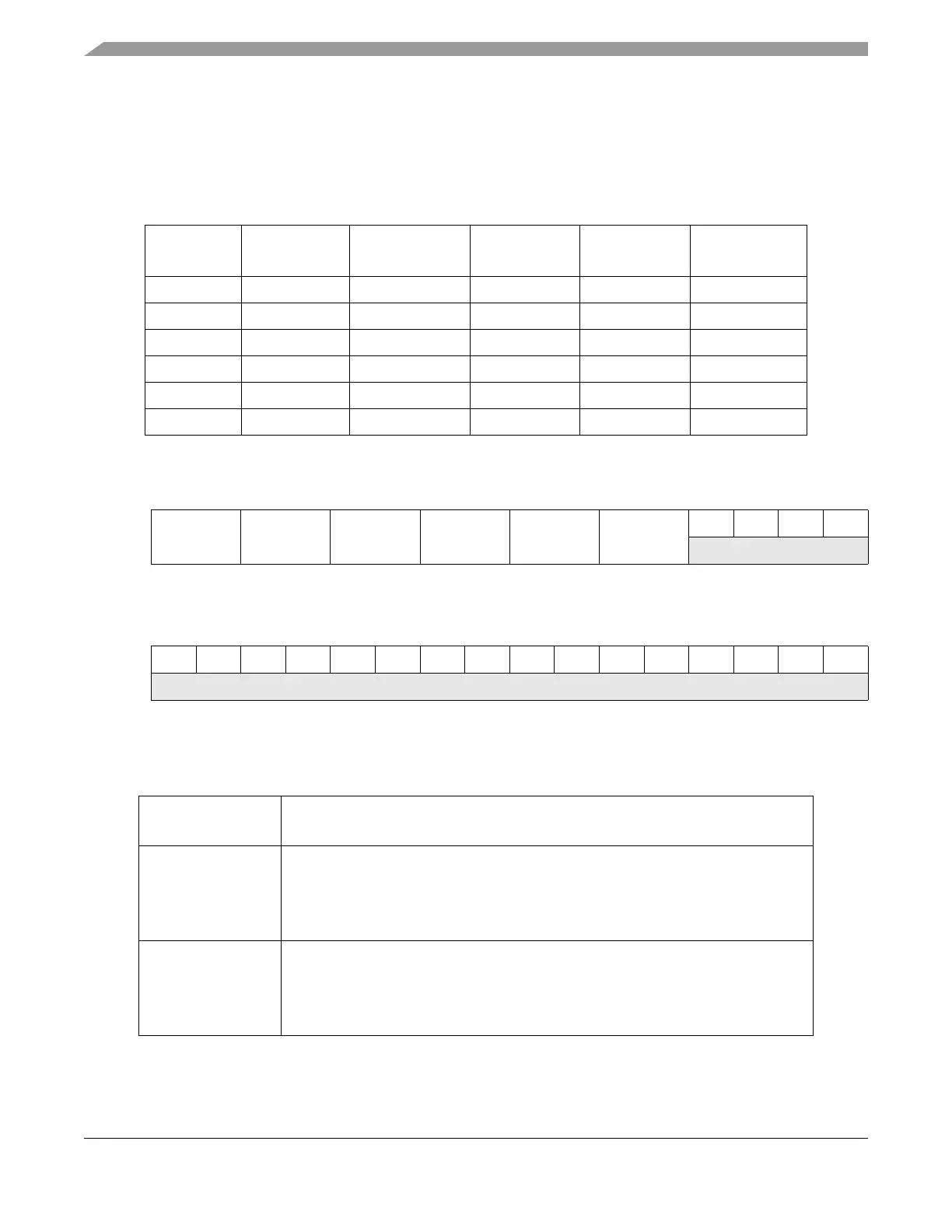
Table 6-47. Trigger Interconnections
TSEL Field
Trigger Value
eQADC CFIFO
EQADC
DMA Channel
eTPUA
Channel
eMIOS
Channel
ETRIG Input
0 0 0 ETPUA[30] EMIOS[10] ETRIG[0]
1 1 2 ETPUA[31] EMIOS[11] ETRIG[1]
2 2 4 ETPUA[29] EMIOS[15] ETRIG[0]
3 3 6 ETPUA[28] EMIOS[14] ETRIG[1]
4 4 8 ETPUA[27] EMIOS[13] ETRIG[0]
5 5 10 ETPUA[26] EMIOS[12] ETRIG[1]
Address: Base + 0x0900 Access: Read / write [0:11]
0123456789101112131415
R
TSEL5 TSEL4 TSEL3 TSEL2 TSEL1 TSEL0
0000
W
Reset
0000000000000000
Address: Base + 0x0900 Access: Read / write [0:11]
16 17 18 19 20 21 22 23 24 25 26 27 28 29 30 31
R
0000000000000000
W
Reset
0000000000000000
Figure 6-131. eQADC Trigger Input Select Register (SIU_ETISR)
Table 6-48. SIU_ETISR Field Descriptions
Register Bit Range
Field Name
Description
0–1
TSEL5
eQADC trigger input select 5. Specifies the input for eQADC trigger 5.
00 GPIO[207]
01 ETPUA[26] channel
10 EMIOS[12] channel
11 ETRIG[1] pin
2–3
TSEL4
eQADC trigger input select 4. Specifies the input for eQADC trigger 4.
00 GPIO[206]
01 ETPUA[27] channel
10 EMIOS[13] channel
11 ETRIG[0] pin