MPC5553/MPC5554 Microcontroller Reference Manual, Rev. 5
12-54 Freescale Semiconductor
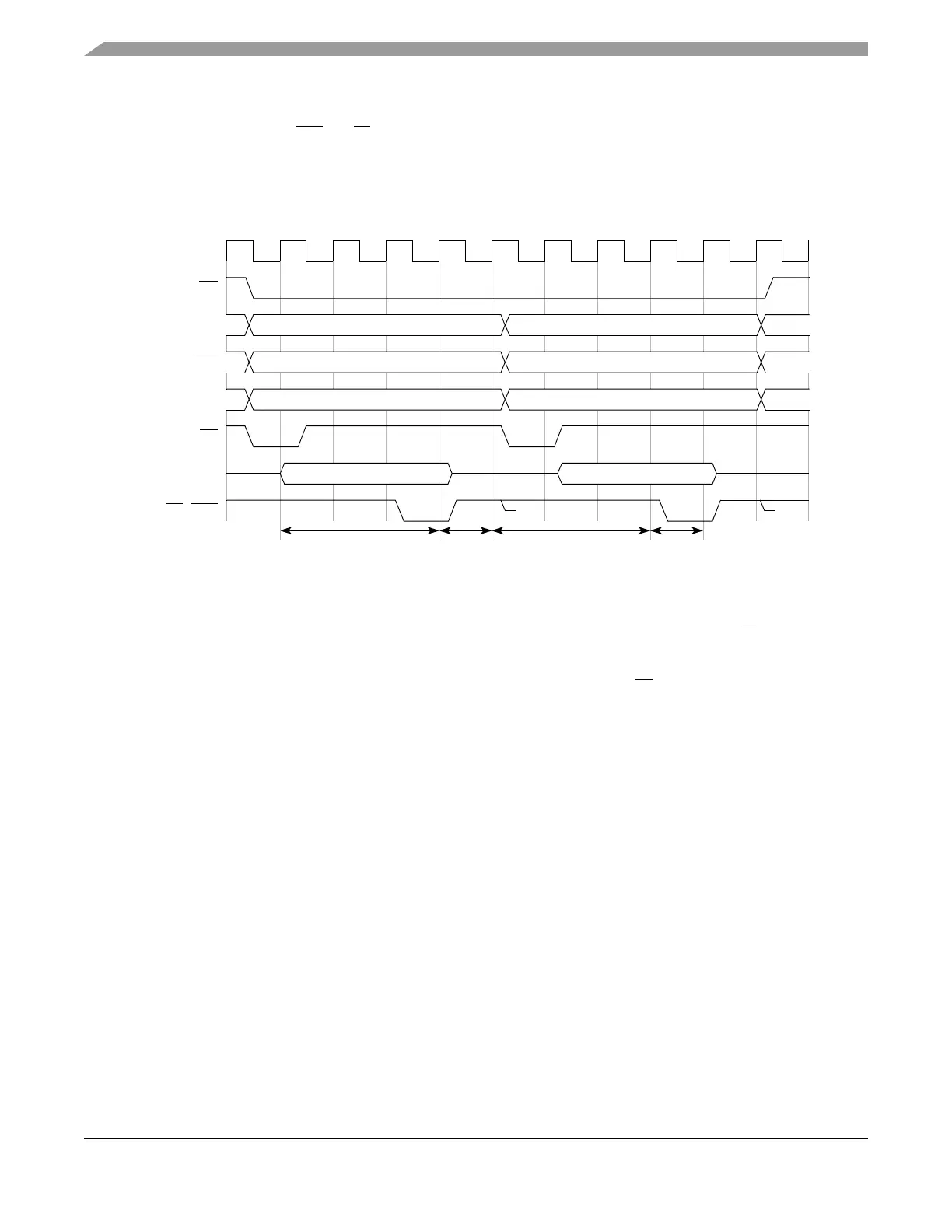
Figure 12-37 shows an example of the termination signals protocol for back-to-back reads to two different
slave devices who properly take turns driving the termination signals. This assumes a system using slave
devices that drive termination signals.
Figure 12-37. Termination Signals Protocol Timing Diagram
12.4.2.10 Bus Operation in External Master Mode
External master mode enables an external master to access the internal address space of the MCU.
Figure 12-38 shows how to connect an MCU to an external master (a second MCU) and a shared SDR
memory to operate in external master mode. Multi-master support is only available in the MPC5554.
Limited support for external master accesses (master/slave systems only) is available in the MPC5553, see
Section 12.5.5, “Dual-MCU Operation with Reduced Pinout MCUs.”
1
Latched version (1 cycle delayed) used for externally driven
TEA and TA.
The EBI drives address and control signals an extra cycle because it uses a latched version of TA
*
This is the earliest that the EBI can start another transfer, in the case of continuing a set of small accesses.
For all other cases, an extra cycle is needed before the EBI can start another TS.
**
CLKOUT
BB
TS
DATA[0:31]
TA
, TEA
ADDR[8:31]
RD_WR
TSIZ[0:1]
Slave 1 Slave 2
**
**
(1 cycle delayed) to terminate the cycle. An external master is not required to do this.
Slave 1
negates
acknowledge
signals and
‘turns off’
Slave 2
negates
acknowledge
signals and
‘turns off’
Slave 2
allowed to
drive
acknowledge
signals
Slave 1
allowed to
drive
acknowledge
signals