MPC5553/MPC5554 Microcontroller Reference Manual, Rev. 5
17-30 Freescale Semiconductor
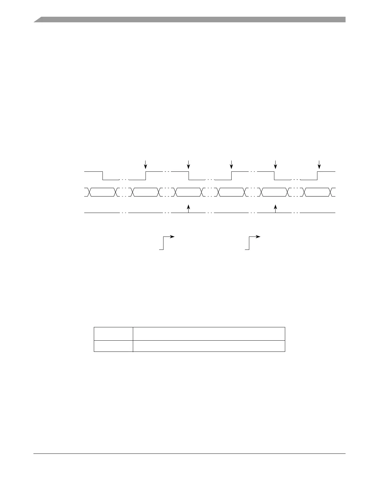
The capture function of register A2 remains disabled until the first leading edge triggers the first input
capture on register B2. When this leading edge is detected, the count value of the selected time base is
latched into register B2; the FLAG bit is not set. When the trailing edge is detected, the count value of the
selected time base is latched into register A2 and, at the same time, the FLAG bit is set and the content of
register B2 is transferred to register B1.
If subsequent input capture events occur while the corresponding FLAG bit is set, registers A2 and B1 will
be updated with the latest captured values and the FLAG will remain set. Registers EMIOS_CADRn and
EMIOS_CBDRn return the value in registers A2 and B1, respectively.
In order to guarantee coherent access, reading EMIOS_CADRn disables transfers between B2 and B1 until
reading EMIOS_CBDRn. After that, transfer is re-enabled.
The input pulse width is calculated by subtracting the value in B1 from A2.
Figure 17-18 shows how the unified channel can be used for input pulse width measurement.
Figure 17-18. Input Pulse Width Measurement Example
17.4.4.4.5 Input Period Measurement Mode (IPM)
The IPM mode allows the measurement of the period of an input signal by capturing two consecutive rising
edges or two consecutive falling edges. Successive input captures are done on consecutive edges of the
same polarity. The edge polarity is defined by the EDPOL bit in the EMIOS_CCRn.
When the first edge of selected polarity is detected, the selected time base is latched into the registers A2
and B2, and the data previously held in register B2 is transferred to register B1. On this first capture the
FLAG line is not set, and the values in registers B1 is meaningless. On the second and subsequent captures,
the FLAG line is set and data in register B2 is transferred to register B1.
When the second edge of the same polarity is detected, the counter bus value is latched into registers A2
and B2, the data previously held in register B2 is transferred to data register B1, and the FLAG bit is set
Table 17-18. Mode of Operation: IPM Mode
MODE[0:6] Unified Channel Mode of Operation
0b0000101 Input Period Measurement Mode
0x000500 0x001000 0x001100 0x001250 0x001525 0x0016A0
Selected
Counter Bus
FLAG
Set Event
BB B
Captured A2
Val ue
2
0xxxxxxx 0xxxxxxx 0x001100 0x001525
Notes:
1
After input filter.
2
Reading EMIOS_CADRn returns the value of A2, writing EMIOS_CADRn writes to A2.
Input Signal
1
EDPOL = 1 A A
B1 Value
3
0x0015250x001100
0xxxxxxx 0xxxxxxx 0x001000 0x0012500x0012500x001000
0xxxxxxx 0x001000 0x001250 0x0016A00x0012500x001000
Captured B2
Val ue
3
Reading EMIOS_CBDRn returns the value of B1, writing EMIOS_CBDRn writes to B1.