MPC5553/MPC5554 Microcontroller Reference Manual, Rev. 5
Freescale Semiconductor 17-47
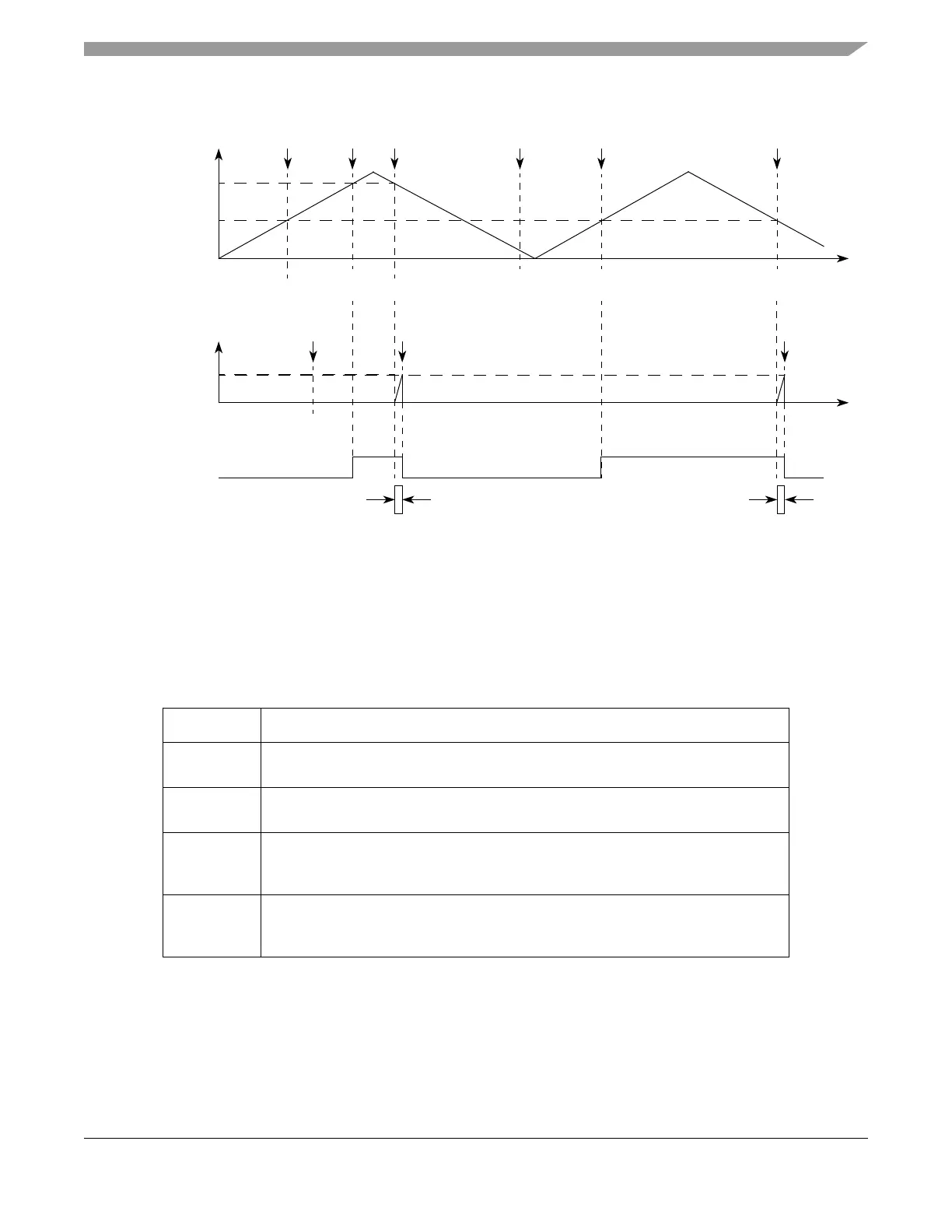
Figure 17-34. Output PWMC with Trailing Dead-time Insertion
17.4.4.4.14 Output Pulse Width Modulation Mode (OPWM)
Registers A1 and B1 define the leading and trailing edges of the PWM output pulse, respectively.
MODE[6] bit controls the transfer from register B2 to B1, which can be done either immediately
(MODE[6] cleared), providing the fastest change in the duty cycle, or at every match of register A1
(MODE[6] set).
Table 17-27. Mode of Operation: OPWM Mode
MODE[0:6] Unified Channel Mode of Operation
0b0100000 Output pulse width modulation
(FLAG set at match of internal counter and comparator B, immediate update)
0b0100001 Output pulse width modulation
(FLAG set at match of internal counter and comparator B, next period update)
0b0100010 Output pulse width modulation
(FLAG set at match of internal counter and comparator A or comparator B, immediate
update)
0b0100011 Output pulse width modulation
(FLAG set at match of internal counter and comparator A or comparator B, next
period update)
Output
Flip-Flop
A1 Match A1 Match
Time
0x000000
0x000303
0x000200
Update to
A1
Selected
MODE[6] = 0
Counter Bus
A1 Match
Notes: 1 Writing EMIOS_An writes to A2.
2 Writing EMIOS_Bn writes to B1.
A2value transferred to A1 according to OUn bit.
B2value transferred to B1 according to OUn bit.
Update to
A1
A1 Match
A1 Value1
0x0002000x0002000x000200
Update to
B1 B1 Match
0x000010
0x000000
EMIOS_CCNTR
B1 Value2
0x000010
Time
B1 Match
0x000303 0x000303
0x000303
0xxxxxxx