MPC5553/MPC5554 Microcontroller Reference Manual, Rev. 5
Freescale Semiconductor 17-49
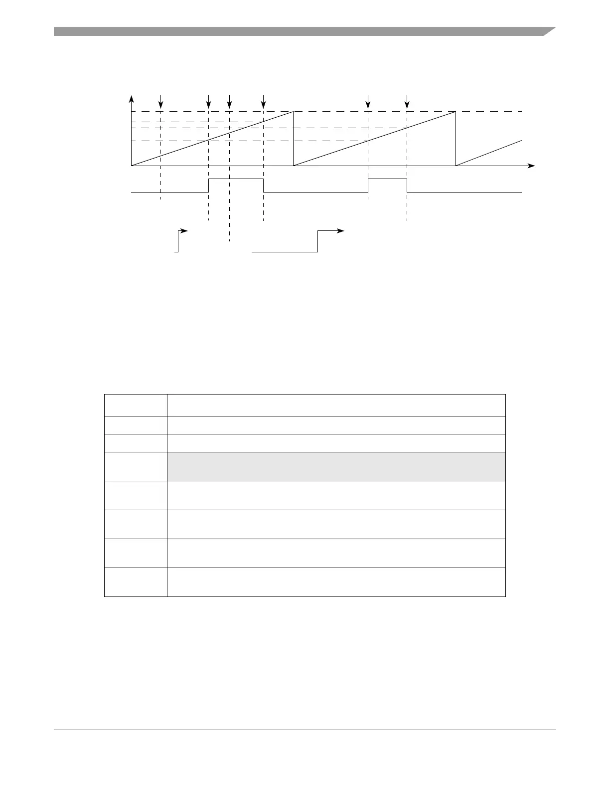
Figure 17-36. Output PWM with Next Period Update
17.4.4.4.15 Modulus Counter, Buffered Mode (MCB) (MPC5553 Only)
The MCB mode provides a time base which can be shared with other channels through the internal counter
buses. Register A1 is double buffered, thus allowing smooth transitions between cycles when changing the
A2 register value asynchronously. The A1 register is updated at the cycle boundary, which is defined as
when the internal counter reaches the value one. Note that the internal counter values are within a range
from one up to register A1 value in MCB mode.
Table 17-28. Mode of Operation: MCB Mode
MODE[0:6] Unified Channel Mode of Operation
0b1010000 Modulus up counter, buffered, internal clock
0b1010001 Modulus up counter, buffered, external clock
0b1010010–
0b1010001
Reserved
0b1010100 Modulus up/down counter, buffered
(FLAG set on one event, internal clock)
0b1010101
Modulus up/down counter, buffered
(FLAG set on one event, external clock)
0b1010110 Modulus up/down counter, buffered
(FLAG set on both events, internal clock)
0b1010111
Modulus up/down counter, buffered
(FLAG set on both events, external clock)
A1 Value1
B1 Value
B2 Value2
0x001000
Output
Flip-Flop
Time
0x000000
B1 Match
0x000200
0xFFFFFF
0x001000
0x000900
0x000200
0x000900
Selected
MODE[6] = 1
Counter Bus
A1 Match B1 Match
0xxxxxxx 0x001000
Notes: 1 Writing EMIOS_An writes to A2.
2 Writing EMIOS_Bn writes to B2.
0x000200
Write to
B2
0x001000
Write to
A1 & B2
A1
Match
0x000900
0x000900
A2value transferred to A1 according to OUn bit.
B2value transferred to B1 according to OUn bit.