MPC5553/MPC5554 Microcontroller Reference Manual, Rev. 5
17-50 Freescale Semiconductor
The MODE[6] bit selects the internal clock source if clear or external if set. When an external clock is
selected, the channel input pin is used as the channel clock source. The active edge of this clock is defined
by EDPOL and EDSEL bits in the EMIOS_CCR channel register.
When entering the MCB mode, if up counter is selected (MODE[4] = 0), the internal counter starts
counting up from its current value to until an A1 match occurs. On the next system clock cycle after an A1
match occurs, the internal counter is set to one and the counter continues counting up. If up/down mode is
selected (MODE[4] = 1), the counter changes direction at the A1 match and counts down until it reaches
one and is then set to count up again. In this mode B1 is set to one and cannot be changed, as it is used to
generate a match to switch from down count to up count.
Note that versus the MC mode, the MCB mode counts between one and the A1 register value. The counter
cycle period in up count mode is equal to the A1 value. In up/down counter mode the period is defined by
the formula: (2 × A1) – 2.
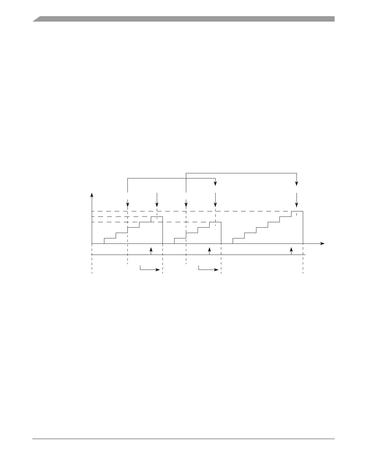
Figure 17-37 illustrates the counter cycle for several A1 values. Register A1 is loaded with the A2 value
at the cycle boundary. Thus any value written to A2 within cycle (n) will be updated to A1 at the next cycle
boundary, and therefore will be used on cycle (n+1). The cycle boundary between cycle (n) and cycle (n+1)
is defined as the first clock cycle of cycle (n+1). Note that flags are set when A1 matches occur.
Figure 17-37. eMIOS MCB Mode Example — Up Operation
NOTE
If a prescaler greater than 1 is used, there are several system clock cycles
between when the flag is asserted and the counter is set to one. This should
be considered when the A value is changed in every cycle, because A1 is
updated on the cycle boundary, which is after the flag is set.
Figure 17-38 illustrates the MCB up/down counter mode. The A1 register is updated at the cycle boundary.
If A2 is written in cycle (n), this new value will be used in cycle (n+1) for the next A1 match.
Time
Write to A2
Match A1 Match A1 Match A1
Write to A2
0x000001
0x000005
0x000006
0x000007
FLAG Set Event
0x000005 0x000007
A2 Value
A1 Value
0x000006
0x000005
0x000007
0x00000
EMIOS_CCNTRn
A2value transferred to A1 according to OUn bit.