MPC5553/MPC5554 Microcontroller Reference Manual, Rev. 5
17-58 Freescale Semiconductor
The EMIOS_OUDR[n] bit can be used to disable the A1 and B1 updates, thus allowing the loading of these
registers to be synchronized with the load of A1 or B1 registers in others channels. Note that by using the
update disable bit, the A1 and B1 registers can be updated in the same counter cycle.
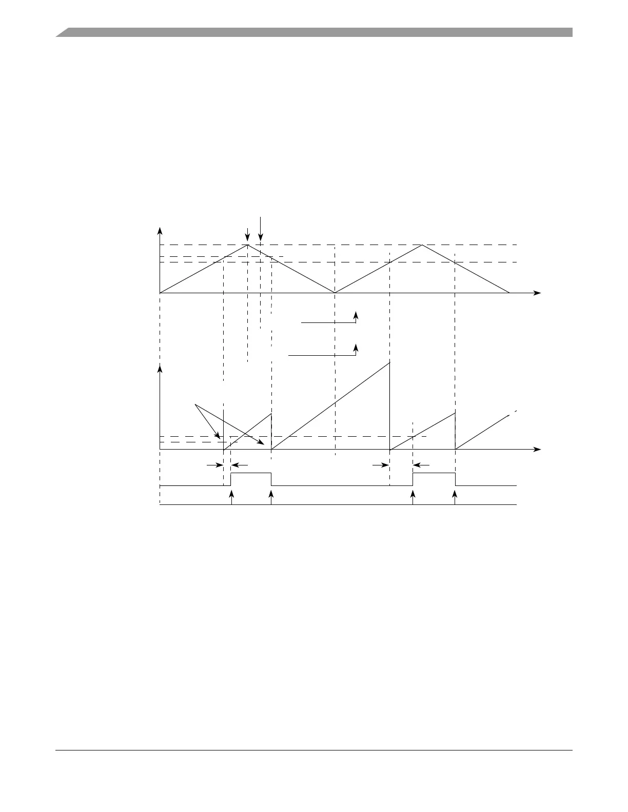
In this mode A1 matches set the internal counter to one. When operating with leading edge dead time
insertion, the first A1 match resets the internal counter to 0x000001. When a match occurs between
register B1 and the internal time base, the output flip-flop is set to the value of the EDPOL bit. In the
following match between A1 and the selected time base, the output flip-flop is set to the complement of
the EDPOL bit. This sequence repeats continuously. Figure 17-47 shows two cycles of a center aligned
PWM signal. Note that both A1 and B1 register values are changing within the same cycle, which allows
the duty cycle and dead time values to be changed at simultaneously.
Figure 17-47. eMIOS PWMCB Mode Example — Lead Dead Time Insertion
As shown in Figure 17-48, when operating with trailing edge dead time insertion the first match between
A1 and the selected time base sets the output flip-flop to the value of the EDPOL bit and resets the internal
counter to 0x000001. In the second match between register A1 and the selected time base, the internal
counter is reset to 0x000001 and B1 matches are enabled. When the match between register B1 and the
selected time base occurs the output flip-flop is set to the complement of the EDPOL bit. This sequence
repeats continuously.
EDPOL = 1
Internal
Internal Counter is
Dead-Time
A1 Value
A2 Value
B1 Value
B2 Value
Selected
0x000002 0x000004
0x000002 0x000004
0x000015
0x000015
0x000013
0x000013
0x000001
0x000002
0x000004
0x000015
0x000013
0x000020
Output Flip-Flop
FLAG Set Event
0x000001
Counter Bus
Time
Time
Time Base
Dead-Time
Set to 1 on A1 Match
Write to B2
Write to A2