MPC5553/MPC5554 Microcontroller Reference Manual, Rev. 5
Freescale Semiconductor 17-57
This mode generates a center aligned PWM with dead time insertion on the leading or trailing edge. A1
and B1 registers are double buffered to allow smooth output signal generation when changing A2 or B2
values asynchronously.
The selected counter bus for a channel configured to OPWMCB mode must be another channel running
in MCB up/down counter mode (refer to Section 17.4.4.4.15, “Modulus Counter, Buffered Mode (MCB)
(MPC5553 Only)”). Register A1 contains the ideal duty cycle for the PWM signal and is compared with
the selected time base. Register B1 contains the dead time value and is compared against the internal
counter. For a leading edge dead time insertion, the output PWM duty cycle is equal to the difference
between register A1 and register B1, and for a trailing edge dead time insertion, the output PWM duty
cycle is equal to the sum of register A1 and register B1. The MODE[6] bit selects between trailing and
leading dead time insertion, respectively.
NOTE
It is recommended that the internal prescaler of the OPWMCB channel be
set to the same value as the MCB channel prescaler, and the prescalers
should also be synchronized. This allows the A1 and B1 registers to
represent the same time scale for duty cycle and dead time insertion.
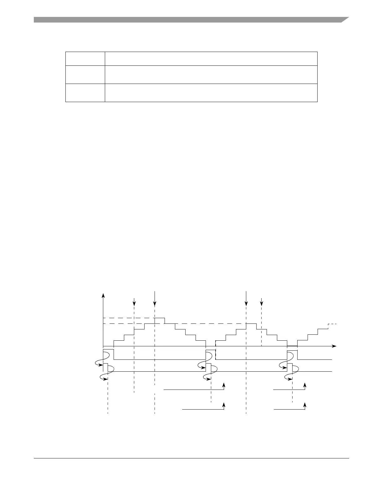
Figure 17-46 illustrates loading of the A1 and B1 registers, which occurs when the selected counter bus
reaches the value one. This counter value defines the cycle boundary. Values written to A2 or B2 within
cycle (n) are loaded into A1 or B1 registers and are used to generate matches in cycle (n+1).
Figure 17-46. eMIOS OPWMCB Mode Example — A1/B1 Register Loading
0b1011110 Center aligned output pulse width modulation, buffered
(FLAG set on both edges, trailing edge dead-time)
0b1011111 Center aligned output pulse width modulation, buffered
(FLAG set on both edges, leading edge dead-time)
Table 17-30. Mode of Operation: OPWMCB Mode (Continued)
MODE[0:6] Unified Channel Mode of Operation
Selected
Time
Write to A2
Match A1 Match A1
Write to A2
0x000001
0x000005
0x000006
0x000015
A1 Value
A2 Value
0x000020
0x000015
Selected Counter = 1
A1/B1 Load Signal
0x000020 0x000016
0x000016
Cycle n Cycle n+1 Cycle n+2
B1 Value
0x000004
B2 Value
0x000004 0x0000060x000005
0x000005 0x000006
Counter
Bus