MPC5553/MPC5554 Microcontroller Reference Manual, Rev. 5
17-56 Freescale Semiconductor
Note that the output disable has a synchronous operation, meaning that the assertion of the output disable
input signal causes the channel output flip-flop to transition to EDPOL at the next system clock cycle. If
the output disable input is negated, the output flip-flop transitions at the following A1 or B1 match.
In Figure 17-44 it is assumed that the output disable input is enabled and selected for the channel (refer to
Section 17.3.1.7, “eMIOS Channel Control Register (EMIOS_CCRn),” for a detailed description of the
ODIS and ODISSL bits and selection of the output disable inputs).
The FORCMA and FORCMB bits allow the software to force the output flip-flop to the level
corresponding to a match on comparators A or B respectively. Similar to a B1 match, FORCMB clears the
internal counter. The FLAG bit is not set when the FORCMA or FORCMB bits are set.
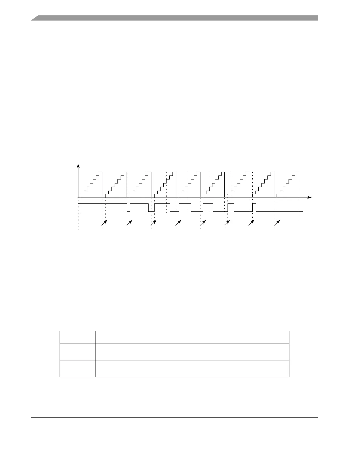
Figure 17-45 illustrates the generation of 100% and 0% duty cycle signals. It is assumed that EDPOL = 0
and the prescaler ratio is 1. Initially A1 = 0x000008 and B1 = 0x000008. In this case, a B1 match has
precedence over an A1 match, thus the output flip-flop is set to the complement of EDPOL. This cycle
corresponds to a 100% duty cycle signal. The same output signal can be generated for any A1 value greater
than or equal to B1.
Figure 17-45. eMIOS OPWFMB Mode Example — 100% to 0% Duty Cycle
A 0% duty cycle signal is generated if A1 = 0 as shown in Figure 17-45 cycle 9. In this case the
B1 = 0x000008 match from cycle 8 occurs at the same time as the A1 = 0x000000 match from cycle 9.
Refer to Figure 17-42 for a description of A1 and B1 match generation for a case where A1 match has
precedence over B1 match and the output signal transitions to EDPOL.
17.4.4.4.17 Center Aligned Output Pulse Width Modulation, Buffered Mode (OPWMCB)
(MPC5553 Only)
Table 17-30. Mode of Operation: OPWMCB Mode
MODE[0:6] Unified Channel Mode of Operation
0b1011100 Center aligned output pulse width modulation, buffered
(FLAG set on trailing edge, trailing edge dead-time)
0b1011101 Center aligned output pulse width modulation, buffered
(FLAG set on trailing edge, leading edge dead-time)
0x000008 0x000007 0x000006 0x000005 0x000004 0x000003 0x000002 0x000001 0x000000
0%
100%
EDPOL = 0
A1 Value
B1 Value
Output Flip-Flop
0x000008
Prescaler = 1
Cycle 1 Cycle 2 Cycle 3 Cycle 4 Cycle 5 Cycle 6 Cycle 7 Cycle 8 Cycle 9
0x000007 0x000006 0x000005 0x000004 0x000003 0x000002 0x000001 0x000000A2 Value
Time
EMIOS_CCNTRn