MPC5553/MPC5554 Microcontroller Reference Manual, Rev. 5
17-62 Freescale Semiconductor
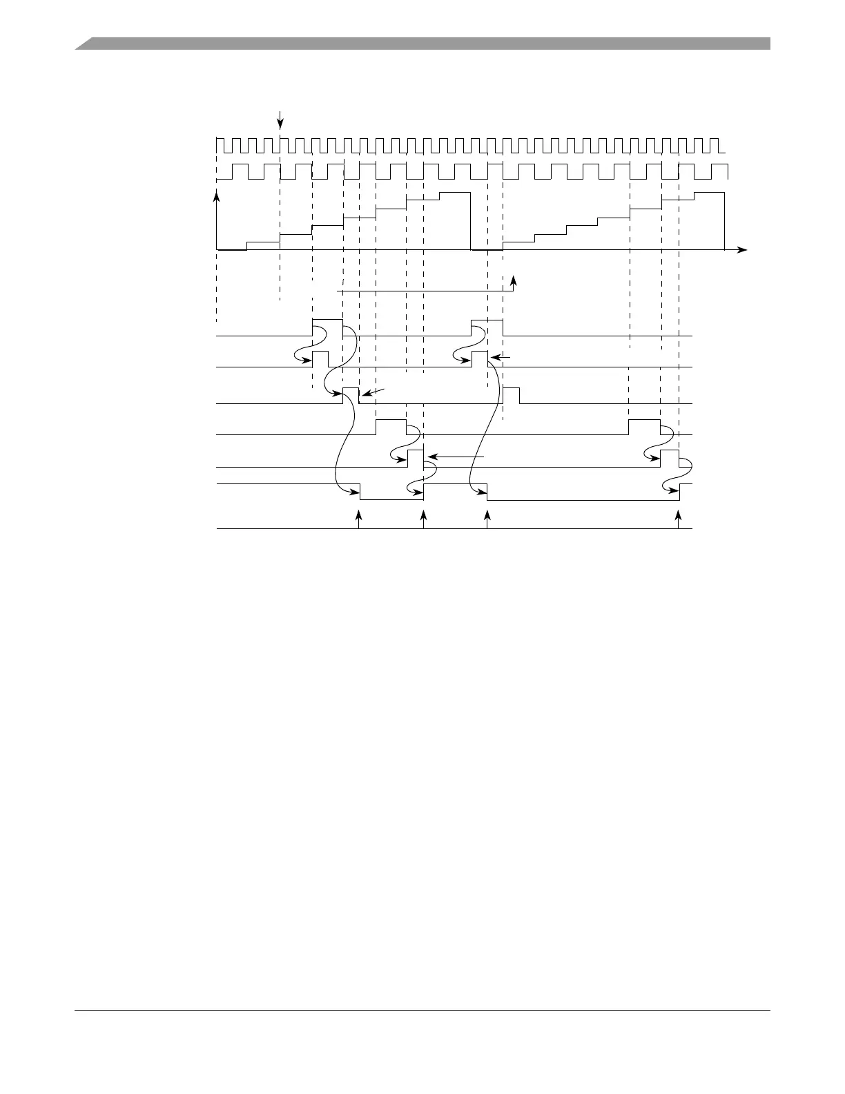
Figure 17-50. eMIOS OPWMB Mode Example — Matches and Flags
Note that the output flip-flop transitions are based on the negative edges of the A1 and B1 match signals.
Figure 17-50 shows the value of A1 being set to zero in cycle (n+1). In this case the match positive edge
is used instead of the negative edge to transition the output flip-flop.
Figure 17-51 illustrates the channel operation for 0% duty cycle. Note that the A1 match signal positive
edge occurs at the same time as the B1 = 8 signal negative edge. In this case the A1 match has precedence
over the B1 match, causing the output flip-flop to remain at the EDPOL value, thus generating a 0% duty
cycle.
1
4
A1 Match Nega-
6
A1 Value 0x000004
A1 Match
Output Flip-Flop
Selected
Time
B1 Match
B1 Match
B1 Value 0x000006
System Clock
Prescaled Clock
A2 Value 0x000000
0x000000
A1 Match Positive Edge Detect
1
8
6
FLAG Bit Set
EDPOL = 0
A1 Match Negative
B1 Match Negative
A1 Match Positive
Edge Detection
Edge Detection
Edge Detection
Negative Edge Detect
Cycle n Cycle n+1
Write to A2
tive Edge Detect
Counter Bus