MPC5553/MPC5554 Microcontroller Reference Manual, Rev. 5
17-64 Freescale Semiconductor
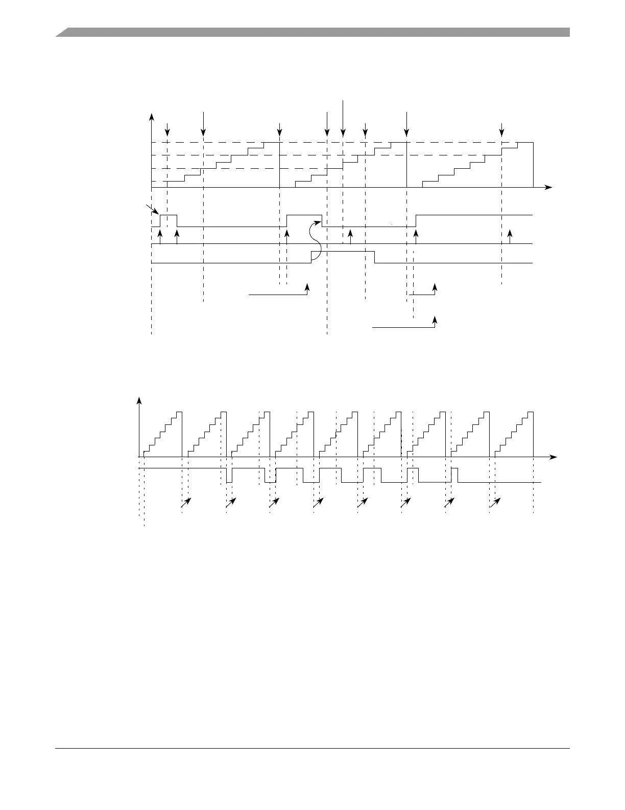
Figure 17-52. eMIOS OPWMB Mode Example — Active Output Disable
Figure 17-53 shows a waveform changing from 100% to 0% duty cycle. In this case EDPOL is zero and
B1 is set to the same value as the period of the selected external time base.
Figure 17-53. eMIOS OPWMB Mode Example — 100% to 0% Duty Cycle
In Figure 17-53 if B1 is set to a value lower than 0x000008 it is not possible to achieve 0% duty cycle by
only changing A1 register value. Because B1 matches have precedence over A1 matches, the output
flip-flop transitions to the compliment of EDPOL at B1 matches. In this example, if B1 = 0x000009, a B1
match does not occur, and thus a 0% duty cycle signal is generated.
Cycle n Cycle n+1 Cycle n+2
A1 Value
B1 Value
B2 Value
0x000008
0x000002
0x000006
0x000008
0x000001
Selected
0x000004
0x000006
MODE[0] = 1
A2 Value
0x000002 0x000004
0x000002
0x000004
0x000006
0x000008 0x000006
Output Flip-Flop
Write to B2
Match A1 Match B1
Match B1
A1/B1
Due to B1 Match
FLAG Set Event
Cycle n-1
Time
Write to A2
Match A1
Write to A2 Match B1
Load Signal
EDPOL = 0
0x000006
Counter Bus
0x000008 0x000007 0x000006 0x000005 0x000004 0x000003 0x000002 0x000001 0x000000
0%
100%
Selected
EDPOL = 0
A1 Value
B1 Value
Output Flip-Flop
0x000008
Prescaler = 1
Cycle 1 Cycle 2 Cycle 3 Cycle 4 Cycle 5 Cycle 6 Cycle 7 Cycle 8 Cycle 9
0x000007 0x000006 0x000005 0x000004 0x000003 0x000002 0x000001 0x000000A2 Value
Time
Counter Bus