MPC5553/MPC5554 Microcontroller Reference Manual, Rev. 5
18-34 Freescale Semiconductor
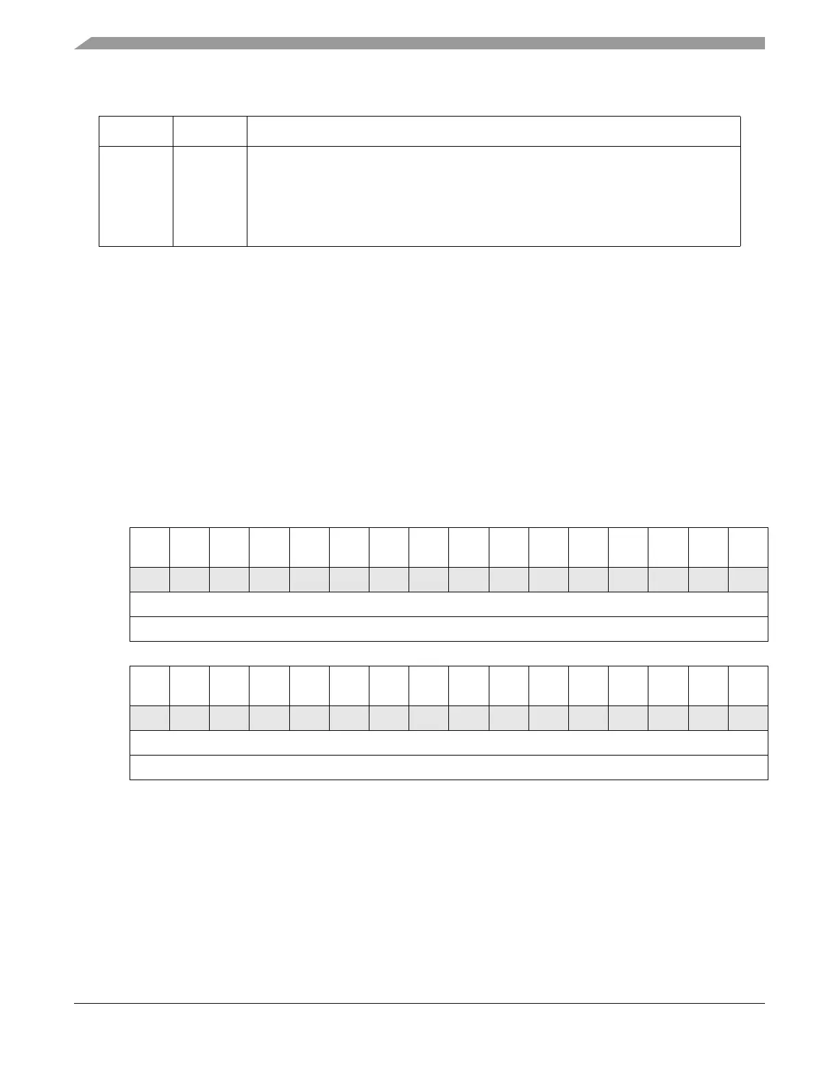
18.4.2.3.2 eTPU Channel Data Transfer Request Status Register (ETPU_CDTRSR)
Data transfer request status from all channels are grouped in ETPU_CDTRSR. The bits are mirrored by
the channels’ status/control registers. For more information on data transfers and channel control registers,
see the eTPU reference manual.
In the MPC5554, eTPU A channels [0:2,12:15,28:29] and eTPU B channels
[0:3,12:15,28:31] are connected to the DMA; in the MPC5553, eTPU
channels [0:2, 14:15] are DMA connected. The data transfer request lines
that are not connected to the DMA controller are left disconnected and do
not generate transfer requests, even if their request status bits are asserted in
registers ETPU_CDTRSR and ETPU_CnSCR. Channels that are not
connected may still have their status bits (DTRSn) cleared by writing a 1 to
the appropriate field.
Table 18-16. ETPU_CISR Field Descriptions
Bits Name Description
0–31 CISn Channel n interrupt status.
0 indicates that channel n has no pending interrupt to the host core.
1 indicates that channel n has a pending interrupt to the host core.
To clear a status bit, the host must write 1 to it.
For details about interrupts refer to the eTPU reference manual.
0123456789101112131415
RDTRS
31
DTRS
30
DTRS
29
DTRS
28
DTRS
27
DTRS
26
DTRS
25
DTRS
24
DTRS
23
DTRS
22
DTRS
21
DTRS
20
DTRS
19
DTRS
18
DTRS
17
DTRS
16
W w1c w1c w1c w1c w1c w1c w1c w1c w1c w1c w1c w1c w1c w1c w1c w1c
Reset0000000000000000
Reg Addr eTPU A: Base + 0x0_0210 / eTPU B: Base + 0x0_0214
16 17 18 19 20 21 22 23 24 25 26 27 28 29 30 31
RDTRS
15
DTRS
14
DTRS
13
DTRS
12
DTRS
11
DTRS
10
DTRS
9
DTRS
8
DTRS
7
DTRS
6
DTRS
5
DTRS
4
DTRS
3
DTRS
2
DTRS
1
DTRS
0
W
w1c w1c w1c w1c w1c w1c w1c w1c w1c w1c w1c w1c w1c w1c w1c w1c
Reset0000000000000000
Reg Addr eTPU A: Base + 0x0_0210 / eTPU B: Base + 0x0_0214
Figure 18-15. eTPU Channel Data Transfer Request Status Register (ETPU_CDTRSR)