MPC5553/MPC5554 Microcontroller Reference Manual, Rev. 5
Freescale Semiconductor 19-15
19.3.2.3 eQADC External Trigger Digital Filter Register (EQADC_ETDFR)
The EQADC_ETDFR is used to set the minimum time a signal must be held in a logic state on the CFIFO
triggers inputs to be recognized as an edge or level gated trigger. The digital filter length field specifies the
minimum number of system clocks that must be counted by the digital filter counter to recognize a logic
state change.
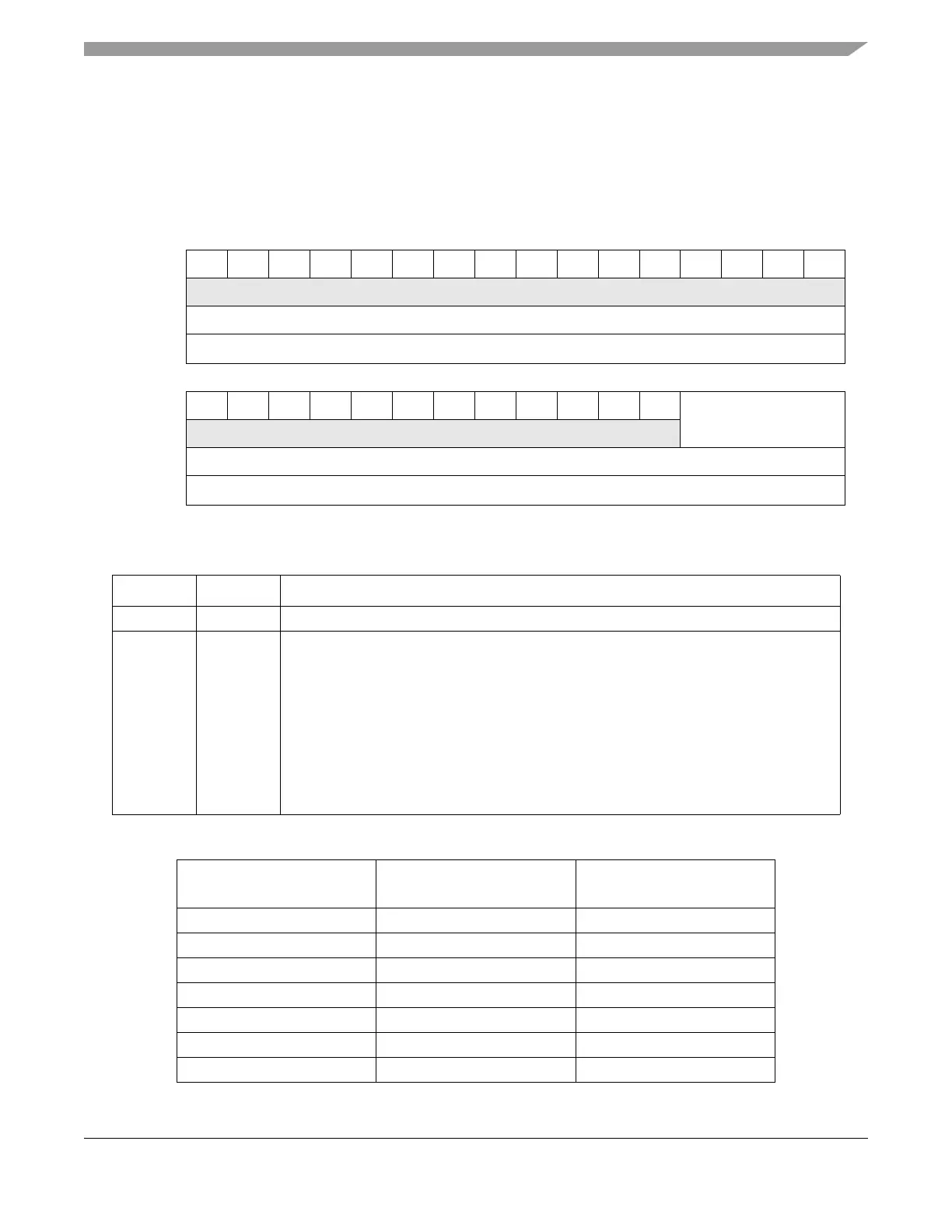
0123456789101112131415
R0000000000000000
W
Reset0000000000000000
Reg Addr
Base + 0x000C
16 17 18 19 20 21 22 23 24 25 26 27 28 29 30 31
R000000000000 DFL
W
Reset0000000000000000
Reg Addr
Base + 0x000C
Figure 19-4. eQADC External Trigger Digital Filter Register (EQADC_ETDFR)
Table 19-5. EQADC_ETDFR Field Description Table
Bits Name Description
0–27 — Reserved.
28–31 DFL
[0:3]
Digital filter length. Specifies the minimum number of system clocks that must be counted
by the digital filter counter to recognize a logic state change. The count specifies the
sample period of the digital filter which is calculated according to the following equation:
Minimum clock counts for which an ETRIG signal needs to be stable to be passed through
the filter are shown in Table 19-6. Refer to Section 19.4.3.4, “External Trigger Event
Detection,” for more information on the digital filter.
Note: The DFL field must only be written when the MODEn of all CFIFOs are configured
to disabled.
Table 19-6. Minimum Required Time to Valid ETRIG
DFL[0:3] Minimum Clock Count
Minimum Time (ns)
(System Clock = 120MHz)
0b0000 2 16.67
0b0001 3 25.00
0b0010 5 41.67
0b0011 9 75.00
0b0100 17 141.67
0b0101 33 275.00
0b0110 65 541.67
FilterPeriod S ystemClockPeriod 2
DFL
1S ystemClockPeriod+=