MPC5553/MPC5554 Microcontroller Reference Manual, Rev. 5
2-34 Freescale Semiconductor
V
SS
Ground P N.A V
SSINT
I / –
V
SS
A1, A2,
A27, A28,
B1, B2,
B27, B28,
C3, C26,
E5, E24,
G7, G22,
H8, H21,
L11:14,
M12:17,
N14:17,
P14:17,
R14:16,
T13,
T16:17,
U12,
U17:18, V7,
V18, AA8,
AA21, AB7,
AB22, AD5,
AF3, AF26,
AG1:2,
AG27:28
AH1:2,
AH27:28
A1, AF1,
B2, AE2,
C3, AD3,
D4, AC4,
D23, C24,
B25, A26,
AD24, AE
25,
AF26, K10,
K11, K12,
K13, L10,
L11, L12,
L13, L14,
L15, L16,
M12, M13,
M14, M15,
M16, N12,
N13, N14,
N15, N16,
P12, P13,
P14, P15,
P16, P17,
R12, R13,
R14, R15,
R16, R17,
T11, T16,
T17, U10,
U16, U17,
AC23
No Connect (NC)
NC
36
No Connect N.A N.A N.A N.A N.A N.A
A19,
B17:19,
C17:19,
E17:23,
G16:21,
H16:20,
J22, J27:28,
K21:22,
K26:28,
L22, L24,
L26:27,
M24, P2,
R2, AA12,
AG17
AC22,
AD23
1
Because more than one signal is often multiplexed to one pin, each line in the signal name column is a separate function. For all MPC5554 I/O
pins the selection of the primary pin function, alternate function, or GPIO is determined in the SIU_PCR registers.
2
Each line in the signal name column corresponds to a separate signal function on the pin. For all device I/O pins, the primary, alternate, or GPIO
signal functions are designated in the PA field of the system integration unit (SIU) PCR registers except where explicitly noted.
3
V
DDE
(fast I/O) and V
DDEH
(slow I/O) power supply inputs are grouped into segments. Each segment of V
DDEH
pins can connect to a separate
3.3–5.0 V ( 5%/–10%) power supply input. Each segment of V
DDE
pins can connect to a separate 1.8–3.3 V ( 10%) power supply, with the
exception of the V
DDE2
and V
DDE3
segments that are shorted together and must use the same power supply input. This segment is labelled V
DDE2
in the BGA map.
Refer to Tab le 2 -3 for a definition of the I/O pins that are powered by each segment.
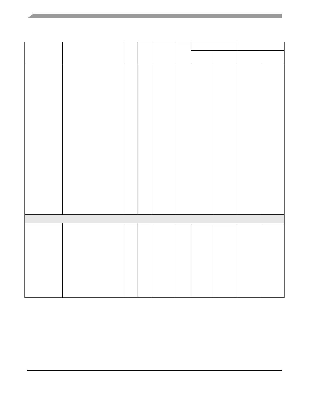
Table 2-2. MPC5554 Signal Properties (Continued)
Signal Names
1
Signal Functions
2
P/
A/
G
I/O
Type
Voltage
3
Pad
Type
4
Status Pin Labels / Package
During
Reset
5
After
Reset
6
496
7
416