MPC5553/MPC5554 Microcontroller Reference Manual, Rev. 5
19-94 Freescale Semiconductor
19.4.6.2 External Multiplexing
The eQADC can use from one to four external multiplexers to expand the number of analog signals that
may be converted. Up to 32 analog channels can be converted through external multiplexer selection. The
externally multiplexed channels are automatically selected by the CHANNEL_NUMBER field of a
command message, in the same way done with internally multiplexed channels. The software selects the
external multiplexed mode by setting the ADC0/1_EMUX bit in either ADC0_CR or ADC1_CR
depending on which ADC will perform the conversion. Figure 19-52 shows the channel number
assignments for the multiplexed mode. There are 4 differential pairs, 40 single-ended, and, at most, 32
externally multiplexed channels that can be selected. Only one ADC can have its ADC0/1_EMUX bit
asserted at a time.
Figure 19-53 shows the maximum configuration of four external multiplexer chips connected to the
eQADC. The external multiplexer chip selects one of eight analog inputs and connects it to a single analog
output, which is fed to a specific input of the eQADC. The eQADC provides three multiplexed address
signals, MA0, MA1, and MA2, to select one of eight inputs. These three multiplexed address signals are
connected to all four external multiplexer chips. The analog output of the four multiplex chips are each
connected to four separate eQADC inputs, ANW, ANX, ANY, and ANZ. The MA pins correspond to the
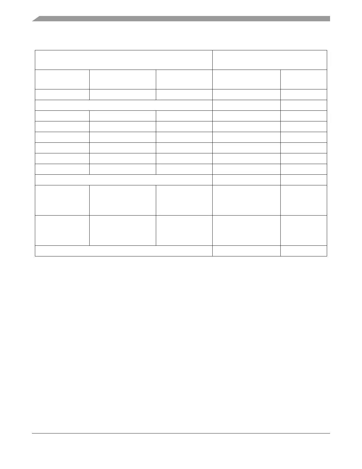
Table 19-52. Multiplexed Channel Assignments
1
1
The two on-chip ADCs can access the same analog input pins but simultaneous conversions are not allowed. Also, when one
ADC is performing a differential conversion on a pair of pins, the other ADC must not access either of these two pins as
single-ended channels.
Input Pins
Channel Number in
CHANNEL_NUMBER Field
Analog
Pin Name
Other Functions Conversion Type Binary Decimal
AN0 to AN7 Single-ended 0000_0000 to 0000_0111 0 to 7
Reserved 0000_1000 to 0000_1011 8 to 11
AN12 to AN39 Single-ended 0000_1100 to 0010_0111 12 to 39
VRH Single-ended 0010_1000 40
VRL Single-ended 0010_1001 41
(VRH–VRL)/2 Single-ended 0010_1010 42
75% x (VRH–VRL) Single-ended 0010_1011 43
25% x (VRH–VRL) Single-ended 0010_1100 44
Reserved 0010_1101 to 0011_1111 45 to 63
ANW
ANX
ANY
ANZ
—
—
—
—
Single-ended
Single-ended
Single-ended
Single-ended
0100_0xxx
0100_1xxx
0101_0xxx
0101_1xxx
64 to 71
72 to 79
80 to 87
88 to 95
DAN0+ and DAN0-
DAN1+ and DAN1-
DAN2+ and DAN2-
DAN3+ and DAN3-
Differential
Differential
Differential
Differential
0110_0000
0110_0001
0110_0010
0110_0011
96
97
98
99
Reserved 0011_0100 to 1111_1111 100 to 255