MPC5553/MPC5554 Microcontroller Reference Manual, Rev. 5
20-14 Freescale Semiconductor
5 CPOL Clock polarity. Selects the inactive state of the serial communications clock (SCK). This
bit is used in both master and slave mode. For successful communication between
serial devices, the devices must have identical clock polarities. When the continuous
selection format is selected (CONT = 1 or DCONT = 1), switching between clock
polarities without stopping the DSPI can cause errors in the transfer due to the
peripheral device interpreting the switch of clock polarity as a valid clock edge. For more
information on continuous selection format, refer to Section 20.4.7.5, “Continuous
Selection Format.”
0 The inactive state value of SCK is low
1 The inactive state value of SCK is high
6 CPHA Clock phase. Selects which edge of SCK causes data to change and which edge
causes data to be captured. This bit is used in both master and slave mode. For
successful communication between serial devices, the devices must have identical
clock phase settings.
0 Data is captured on the leading edge of SCK and changed on the following edge
1 Data is changed on the leading edge of SCK and captured on the following edge
7 LSBFE LSB first enable. Selects if the LSB or MSB of the frame is transferred first. This bit is
only used in master mode.
0 Data is transferred MSB first
1 Data is transferred LSB first
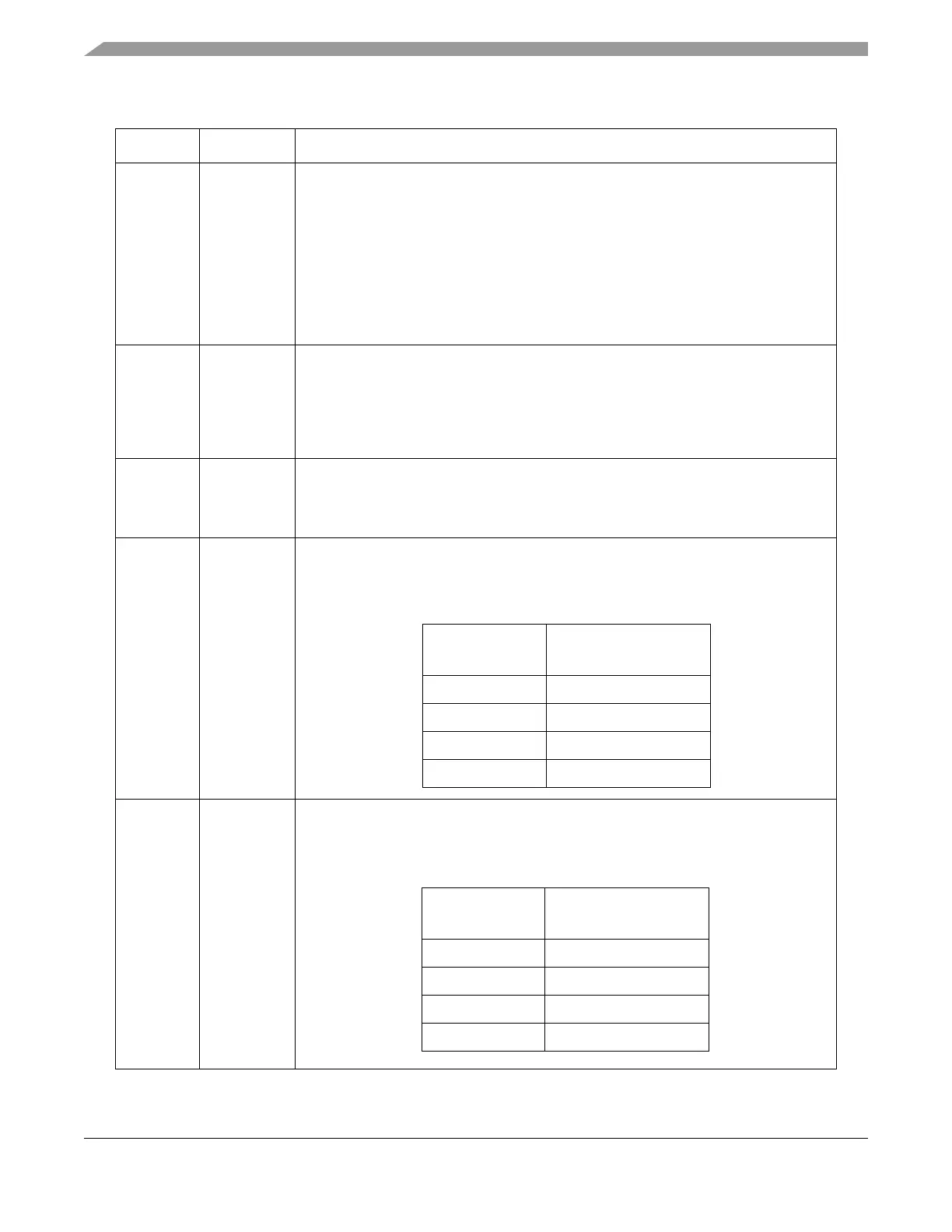
8–9 PCSSCK
[0:1]
PCS to SCK delay prescaler. Selects the prescaler value for the delay between
assertion of PCS and the first edge of the SCK. This field is only used in master mode.
The table below lists the prescaler values. The description for bitfeild CSSCK in
Table 20-5 details how to compute the PCS to SCK delay.
10–11 PASC
[0:1]
After SCK delay prescaler. Selects the prescaler value for the delay between the last
edge of SCK and the negation of PCS. This field is only used in master mode. The table
below lists the prescaler values. The description for bitfeild ASC in Tabl e 2 0-5 details
how to compute the after SCK delay.
Table 20-5. DSPIx_CTARn Field Description (Continued)
Bits Name Description
PCSSCK
PCS to SCK Delay
Prescaler Value
00 1
01 3
10 5
11 7
PASC
After SCK Delay
Prescaler Value
00 1
01 3
10 5
11 7