MPC5553/MPC5554 Microcontroller Reference Manual, Rev. 5
20-18 Freescale Semiconductor
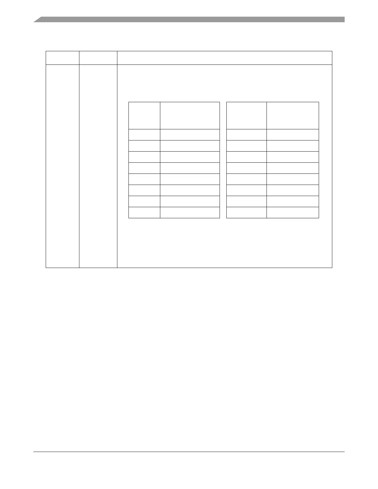
24–27 DT
[0:3]
Delay after transfer scaler. The DT field selects the delay after transfer scaler. This field
is only used in master mode. The delay after transfer is the time between the negation
of the PCS signal at the end of a frame and the assertion of PCS at the beginning of the
next frame. The table below lists the scaler values.
The delay after transfer is a multiple of the system clock period and it is computed
according to the following equation:
Note: See Section 20.4.6.4, “Delay after Transfer (tDT),” for more details
Table 20-5. DSPIx_CTARn Field Description (Continued)
Bits Name Description
DT
Delay after Transfer
Scaler Value
DT
Delay after
Transfer Scaler
Value
0000 2 1000 512
0001 4 1001 1024
0010 8 1010 2048
0011 16 1011 4096
0100 32 1100 8192
0101 64 1101 16384
0110 128 1110 32768
0111 256 1111 65536
t
DT
1
f
SYS
-----------
PDT Prescaler value DT Scaler value=