MPC5553/MPC5554 Microcontroller Reference Manual, Rev. 5
21-10 Freescale Semiconductor
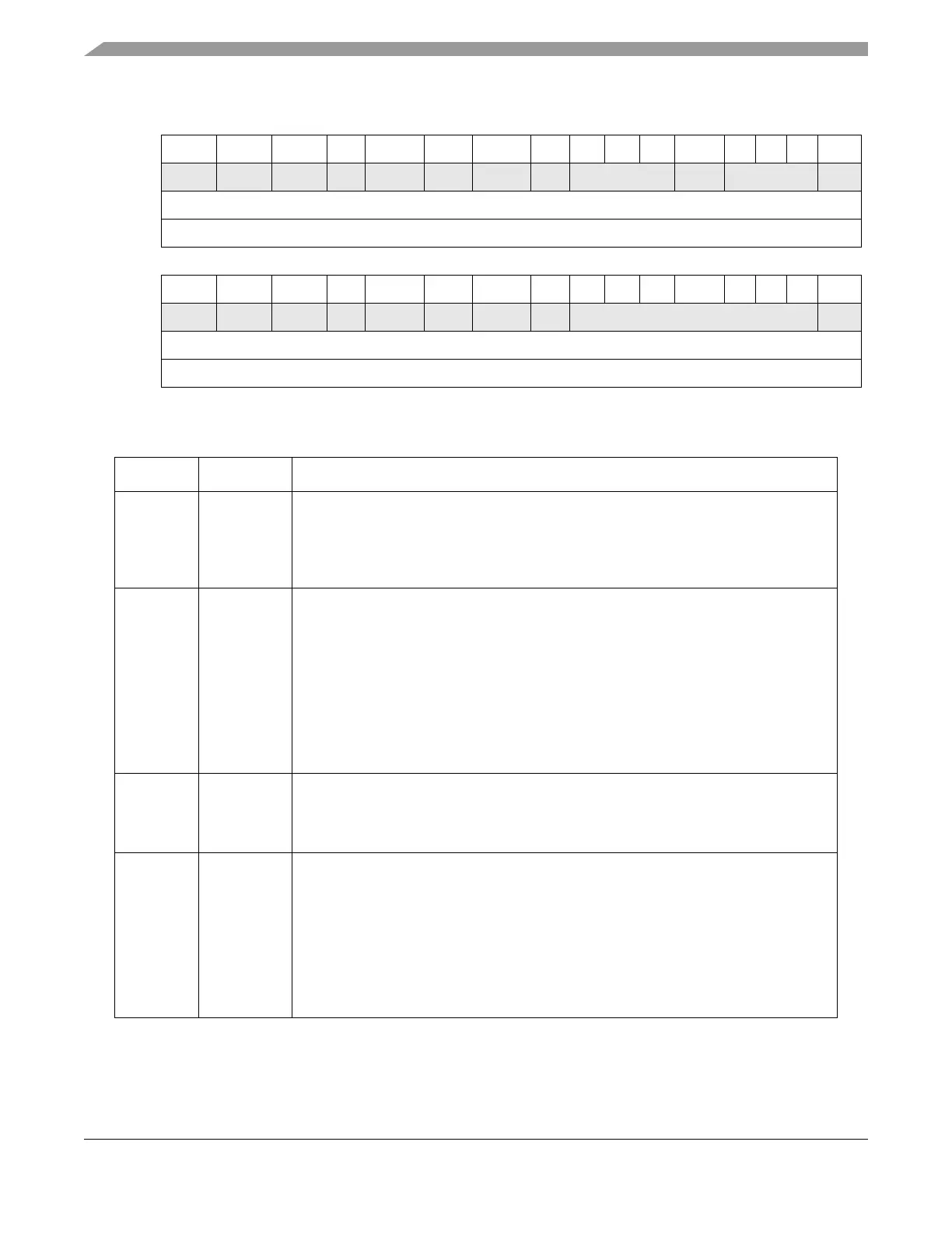
0 1 2 3 4 5 6 7 8 9 10 11 12 13 14 15
R TDRE TC RDRF IDLE OR NF FE PF 0 0 0 BERR 0 0 0 RAF
W w1c w1c w1c w1c w1c w1c w1c w1c w1c
Reset 1 1 0 0 0 0 0 0 0 0 0 0 0 0 0 0
Reg Addr Base + 0x0008
16 17 18 19 20 21 22 23 24 25 26 27 28 29 30 31
R RXRDY TXRDY LWAKE STO PBERR CERR CKERR FRC 0 0 0 0 0 0 0 OVFL
W w1c w1c w1c w1c w1c w1c w1c w1c w1c
Reset 0 0 0 0 0 0 0 0 0 0 0 0 0 0 0 0
Reg Addr Base + 0x0008
Figure 21-5. eSCI Status Register (ESCIx_SR)
Table 21-6. ESCIx_SR Field Descriptions
Bits Name Description
0 TDRE Transmit data register empty flag. TDRE is set when the transmit shift register receives
a byte from the eSCI data register. When TDRE is 1, the data register (ESCIx_DR) is
empty and can receive a new value to transmit. Clear TDRE by writing 1 to it.
0 No byte transferred to transmit shift register
1 Byte transferred to transmit shift register; transmit data register empty
1 TC Transmit complete flag. TC is set low when there is a transmission in progress or when
a preamble or break character is loaded. TC is set high when the TDRE flag is set and
no data, preamble, or break character is being transmitted. When TC is set, the TXD out
signal becomes idle (logic 1).
After the device is switched on (by clearing the MDIS bit, see Section 21.3.3.2, “eSCI
Control Register 2 (ESCIx_CR2),” a preamble is transmitted; if no byte is written to the
the SCI data register then the completion of the preamble can be monitored using the
TC flag. Clear TC by writing 1 to it.
0 Transmission in progress
1 No transmission in progress. Indicates that TXD out is idle.
2 RDRF Receive data register full flag. RDRF is set when the data in the receive shift register
transfers to the eSCI data register. Clear RDRF by writing 1 to it.
0 Data not available in eSCI data register
1 Received data available in eSCI data register
3 IDLE Idle line flag. IDLE is set when 10 consecutive logic 1s (if M = 0) or 11 consecutive logic
1s (if M = 1) appear on the receiver input. After the IDLE flag is cleared, a valid frame
must again set the RDRF flag before an idle condition can set the IDLE flag. Clear IDLE
by writing 1 to it.
0 Receiver input is either active now or has never become active since the IDLE flag was
last cleared
1 Receiver input has become idle
Note: When the receiver wake-up bit (RWU) is set, an idle line condition does not set
the IDLE flag.