OPERATION
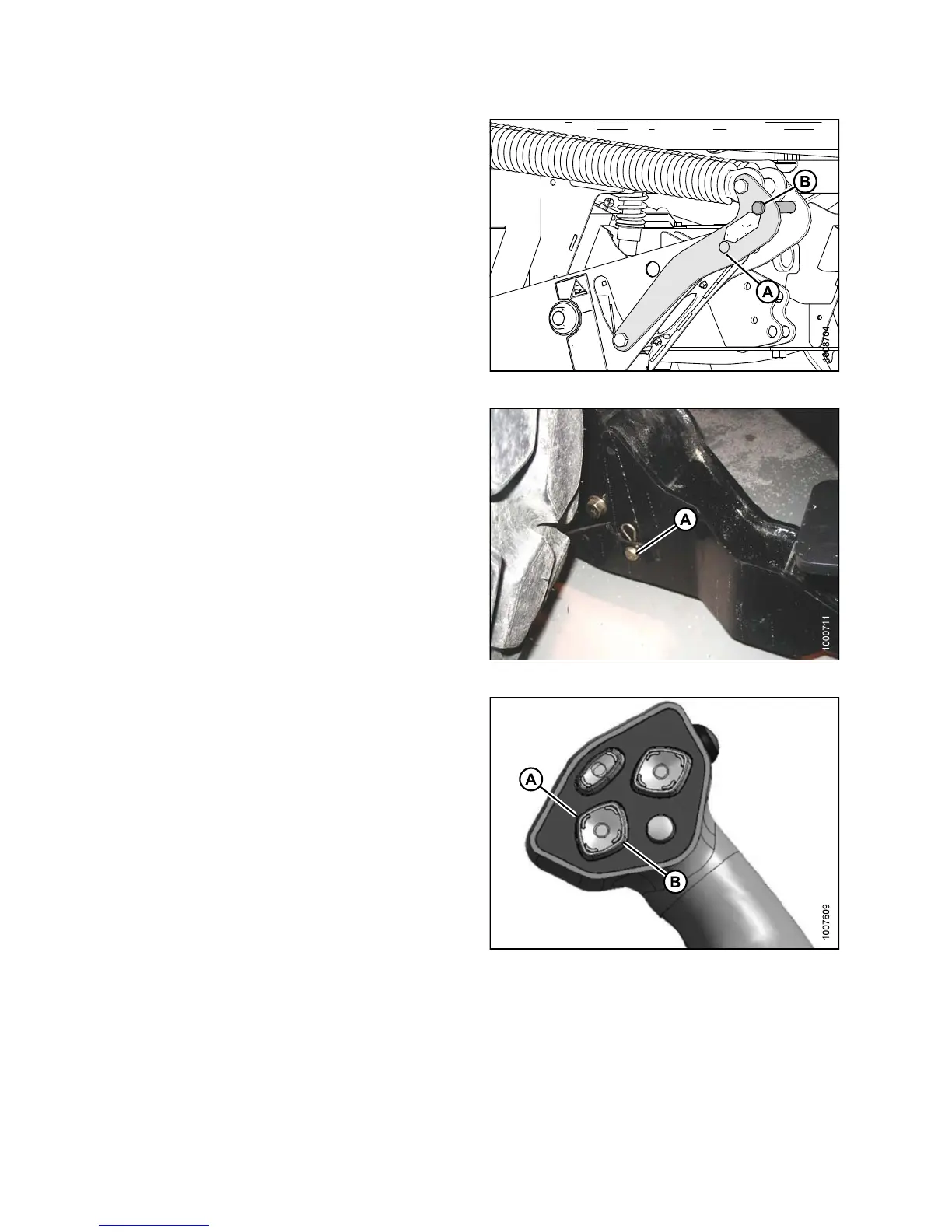
7. Remove float pin from engaged position (A) and insert
in storage location (B). Secure with lynch pin.
Figure 4.40: Lift Arms
8. Remove pins (A) from lower end of lift linkages.
NOTE:
Pins (A) are also used to secure weight box to
windrower linkage.
9. Release the safety props on the header lift cylinders.
Refer to 4.4.1 H eader Safety Props, page 193.
10. Start engine and lower header down onto the
transport wheels.
Figure 4.41: Lift Arms
11. Use the HEADER TILT switches to release load on the
center-link if necessary.
12. Shut down engine and remove k ey from ignition.
Figure 4.42: Ground Speed Lever (GSL)
A-He
ader Tilt Down
B-He
ader Tilt Up
147649 180 Revision A