OPERATION
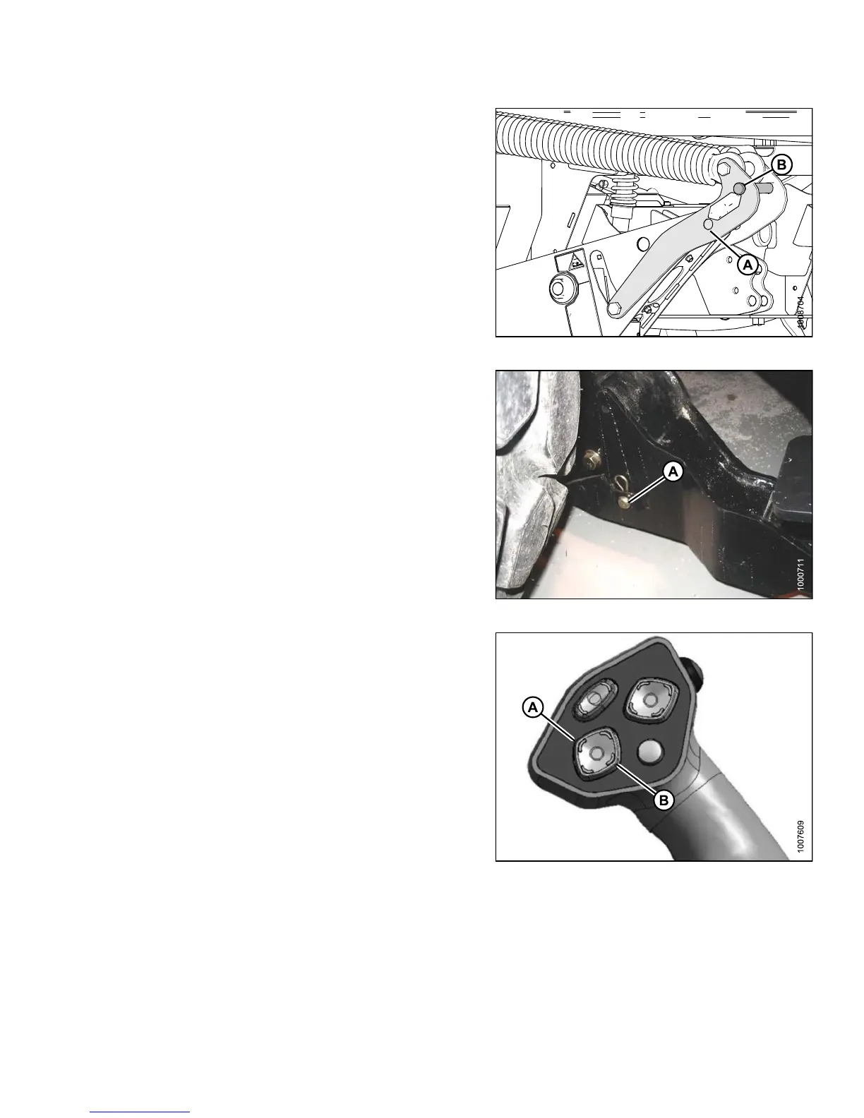
7. Remove float pin from engaged position (A) and insert
instoragelocation(B).Securewithlynchpin.
Figure 4.66: Lift Arms
8. Remove pins (A) from lower end of lift linkages.
NOTE:
Pins (A) are also used to secure weight box to
windrower linkage.
9. Release the safety props on the header lift cylinders.
Refer to 4.4.1 Header Safety Props, page 193.
10. Start engine and lower header down onto the
transport wheels.
Figure 4.67: Lift Arms
11. Use the HEADER TILT switches to release load on the
center-link if necessary.
12. Shut down engine and remove key from ignition.
Figure 4.68: Ground Speed Lever (GSL)
A-He
ader Tilt Down
B-He
ader Tilt Up
147649 189 Revision A