OPERATION
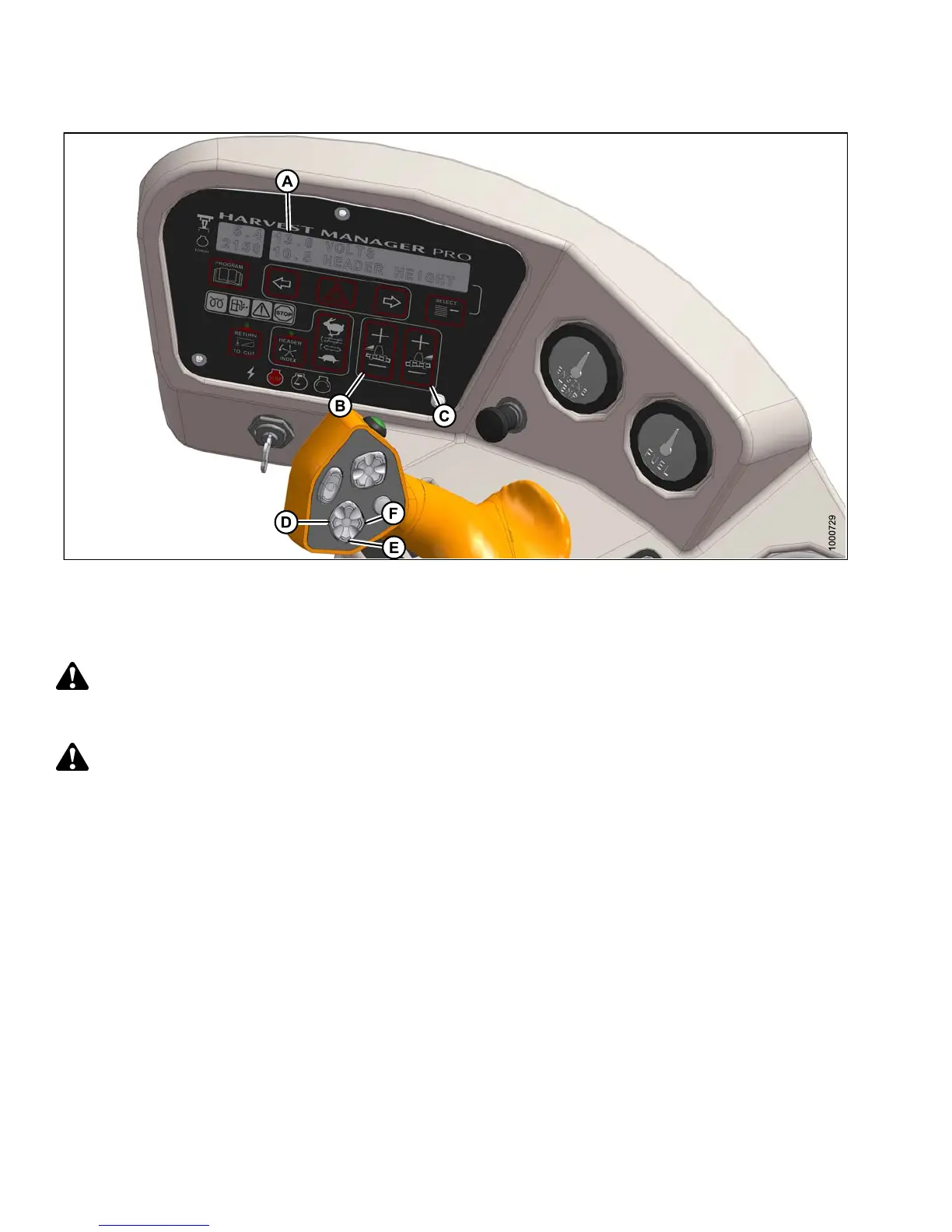
Figure 4.77: Cab Display Module (CDM) Float Adjustment
A - CDM Display B - Left Float Adjustment C - Right Float Adjustment
D - Header Tilt Down E - Header Lower F - Head er Tilt Up
Check header float as fo llows:
DANGER
To avoid bodily injury or death from unexpected startup of the machine, always stop the engine and remove
the key from the ignition before leaving the operator’s seat for any reason.
CAUTION
Check to be
sure all bystanders have cleared the area.
1. Start the engine.
2. Using HEADER TILT switches (D, F), set center-link to mid-range position (5.0 on CDM [A]).
3. Using H EADER DOWN switch (E), lower h ea d er fully with lift cy lind e rs fully retracte d.
4. Set left (B) and r igh t (C) float fine adjustments on CDM to approximately 5.0 as follows:
a. Using FLOAT SELECTOR switch (B), push + to increase float or – to decrease float on left side of header.
CDM display (A) will ind ica te s ele cted float for left side, for example (5.0 L FLOAT R XX.X).
b. Repeat for right side float with sw itch (C). Display will indicate float for both sides, for
example ( 5.0 L FLOAT R 5.0).
5. Shut down engine and remove key.
6. Grasp the divider rod and lift. The force to lift should be as noted in the following table and should be
approximately the same at both ends.
147649 196 Revision A