OPERATION
Header
Force Required to Lift Header at the Ends with Lift Cylinder Fully Retracted
Auger
75–85 lbf (335
–380 N)
Rotary
95–105 lbf (426–471 N)
Draper
75–85 lbf (335 – 38 0 N) with stabilizer/transport wheels rais ed (if eq u ipp e d)
Adjusting F
loat Using Drawbolts
Coarse float adjustment is done using the drawbolts located on either side of the windrower.
If necessary, coarse adjust the float with the drawbolts as follows:
CAUTION
Check to be sure all by stan d e rs have cleared the area.
1. Start engine.
2. Using HEADER UP (A) switch on ground speed
lever (GSL), raise the header fully, shut down engine,
and remove key.
Figure 4.78: GSL
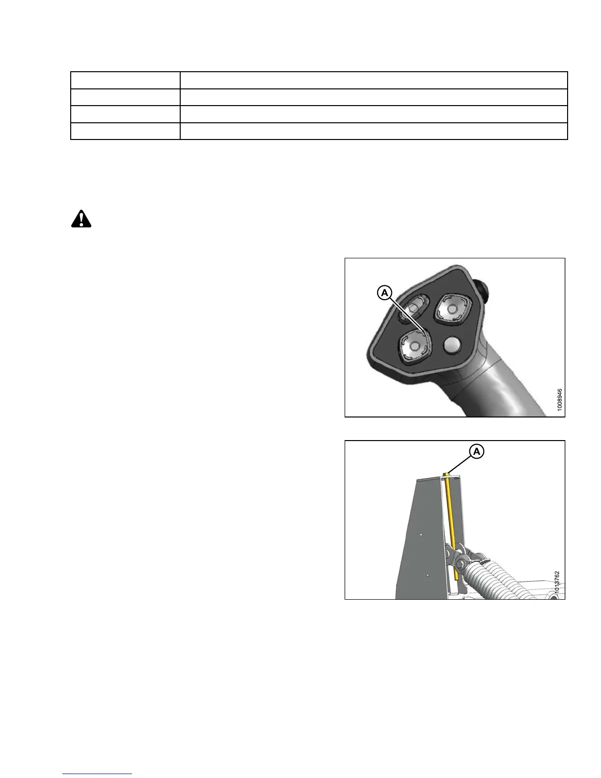
3. Turn drawbolt (A) clockwise to increase float (m akes
header lighter) or counterclockwise to decrease float
(makes header heavier).
4. Recheck the header float.
Figure 4.79: Header Float Adjustment
147649 197 Revision A