OPERATION
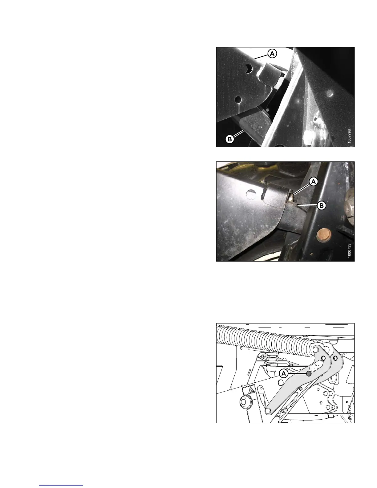
8. Start engine and lower header onto ground until
member (A) lifts off link (B) on both sides.
9. Stop engine and remove key.
Figure 4.87: Lift Linkage
10. On high side, remove nut, washer, and bolt (A) that
attaches shims (B) to link.
11. Remove one or both shims (B) and reinstall the
hardware (A).
12. Start engine and raise header fully.
13. Stop engine and remove key from ignition.
14. M ove float pins to disengaged position.
15. Start engine and set header approximately 6 in. (150
mm) off ground and check that member (A) is against
link (B). Stop engine and remove key from ignition.
16. Measure distance to ground at both ends of header.
17. If additional levelling is required , repeat ste p s 6 to 9
and install the removed shim on the opposite linkage.
NOTE:
If required, additional shims are available from
your Dealer.
Figure 4.88: Lift Linkage
18. O nce header i
s level, return float pins to their engaged
position (A)
.
NOTE:
Float does NOT require adjustmen t after
levelling header.
Figure 4.89: Float Pins – Engaged
147649 201 Revision A