OPERATION
CAUTION
Check to be sure a ll bystanders have cleared the area.
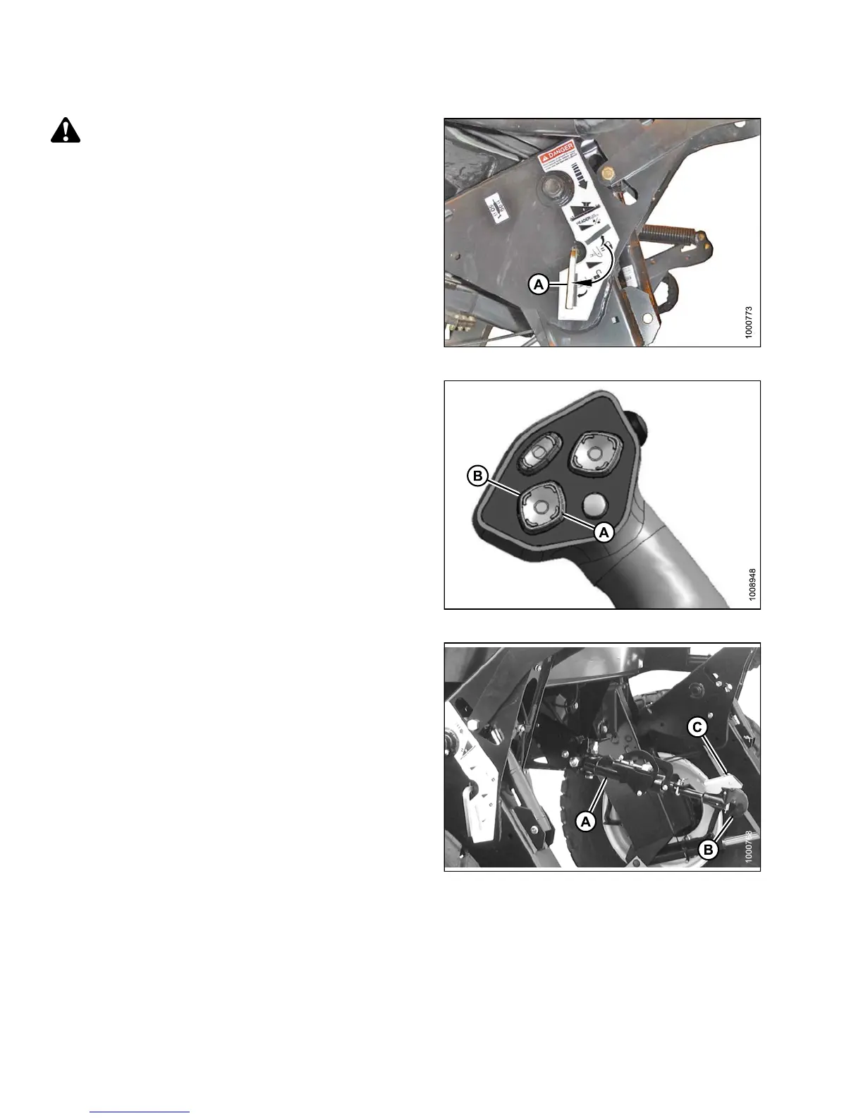
8. Disengage safety props by turning lever (A) away from
header to raise safety prop until lever locks into vertical
position. Repeat for opp osite cylinder.
9. Start engine, choose a level area, and lower header to
the ground.
Figure 4.205: Safety P rops
10. Activate h
eader tilt up (A) and header tilt down (B)
cylinder s
witches on GSL to release load on
center-l
ink cylinder.
Figure 4.206: GSL
11. Stop en
gine and remove key from ignition.
12. Lift h
ook release (C) and lift hook (B) off header pin.
NOTE:
If optional center-link self-alignment kit is
installed, lift release (C) and then operate the
link lift cylinder with reel up switch on GSL to
disengage the center-link from the header.
Figure 4.207: Hydraulic Center-Link
147649 252 Revision A