OPERATION
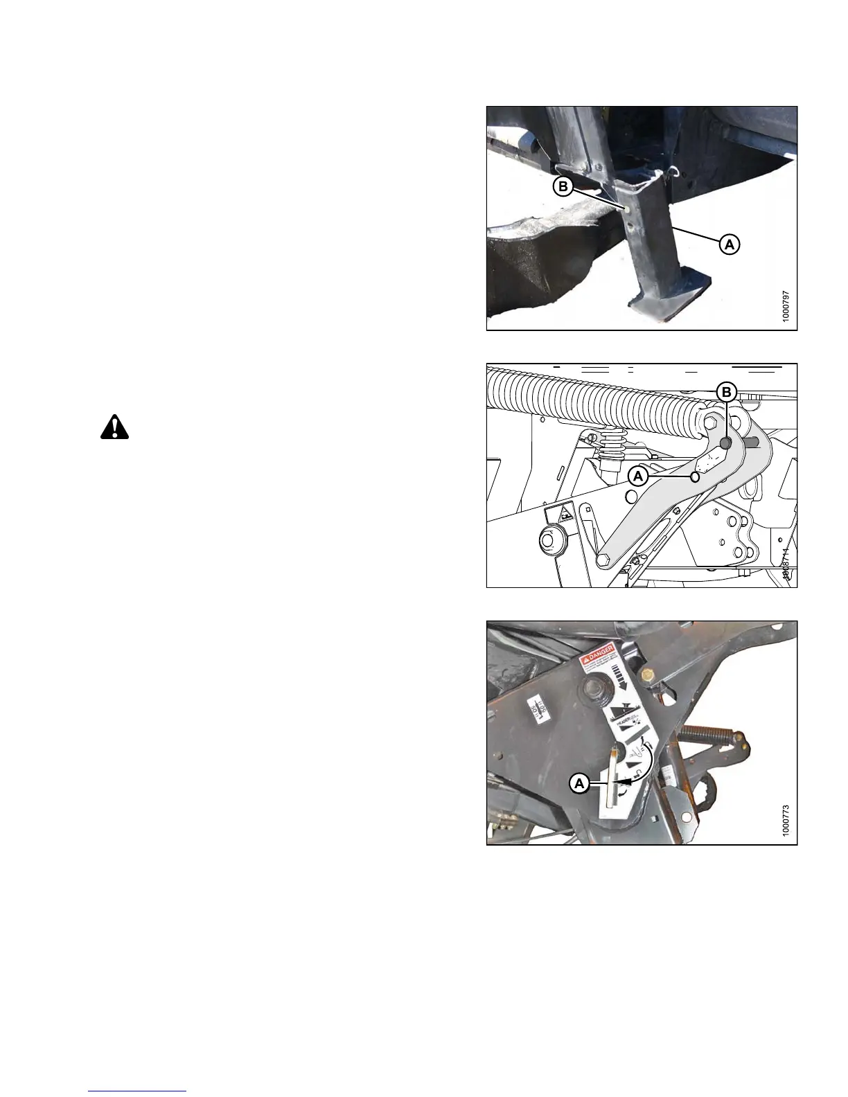
6. Lower th e header stand (A) by pullin g clevis pin (B),
inverting sta nd , and relocating on b racket. Reinsert
clevis pin (B) an d secure with hairp in.
Figure 4.213: Header Stand
7. Remove clevis pin from linkage (A) to disengage float
springs and insert in storage hole ( B). Secure with
lynch pin. Repeat for opposite linkage.
CAUTION
To prevent damage to the lift system when lowering
header lift linkages without a header or weight
box attached to the windrower, ensure the float
engagement pin is installed in storage position (B)
and NOT in engaged position (A).
Figure 4.214: Header Float Linkage
8. Disengage safety props by turning lever (A) away from
header to raise safety prop until lever locks into vertical
position. Repeat for opposite cylinder.
9. Start engine, choose a level area, and lower header to
the ground. Stop engine and remove key.
Figure 4.215: Safety Prop
147649 255 Revision A