OPERATION
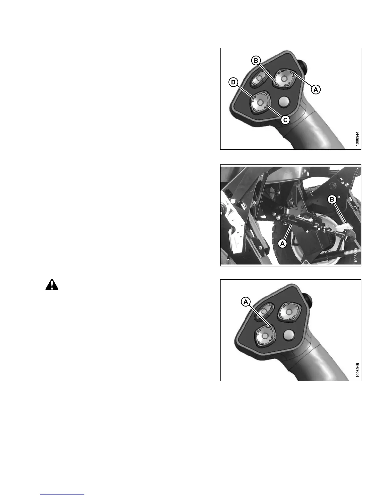
5. Use the following GSL functions to position the
center-link hook above the header attachment pin:
• Reel up (A) to raise the center-link
• Reel down (B) to lower the center-link
• Header tilt up (C) to retract the center-link
• Header tilt down (D) to extend the center-link
Figure 4.224: GSL
6. Adjust position of the center-link cylinder (A) with the
reel up and reel down switches on the GSL until the
hook is positioned above the header attachment pin.
IMPORTAN T:
Hook release must be down to enable self-locking
mechanism. If the release is open (up), manually
push it down after hook engages header pin.
7. Lower center-link (A) onto the header with reel down
switch until it locks into position ( ho ok release [B]
is down).
8. Check that center-link is locked onto header by
pressingthereelupswitchontheGSL.
Figure 4.225: Hydraulic C enter-Link
CAUTION
Check to be sure all bystanders have cleared the area.
9. Press the header up switch (A) to raise header to
maximum height.
NOTE:
If one end of the header does NOT fu lly raise,
rephase the lift c ylin de rs as follows :
a. Press and hold the header up switch until both
cylinders stop moving.
b. Continue to hold the switch for 3–4 seconds.
Cylinders are now phased.
NOTE:
It may be necessary to repeat this procedure if
there is air in the system.
Figure 4.226: GSL
147649 259 Revision A