MAINTENANCE AND S ERVICING
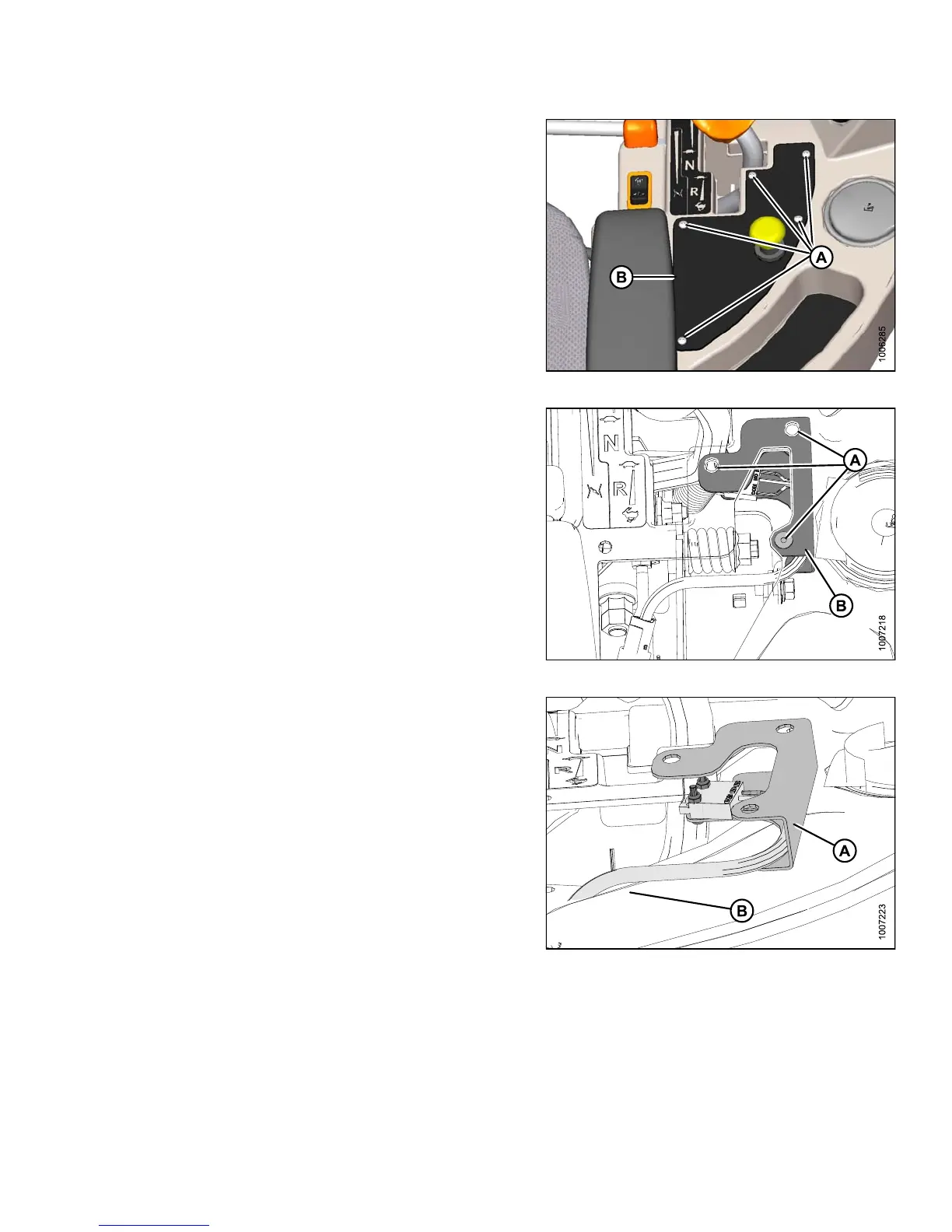
2. Remove the five sc rews (A) se c uring t he co ntrol
panel (B) to the console.
3. Remove the control panel (B) and store in the tray.
Figure 5 .28: Header Control Panel
4. Remove the three rubber nuts (A) securing t he switch
support plate (B) to the console.
NOTE:
For clarit
y, console in the image was made
transpare
nt to show the switch support plate (B).
Figure 5.29: Console (Transparent)
5. Move the switch support plate (A) on top of the
console (B).
Figure 5.30: Switch Support Plate
147649 323 Revision A