MAINTENANCE AND SERVICING
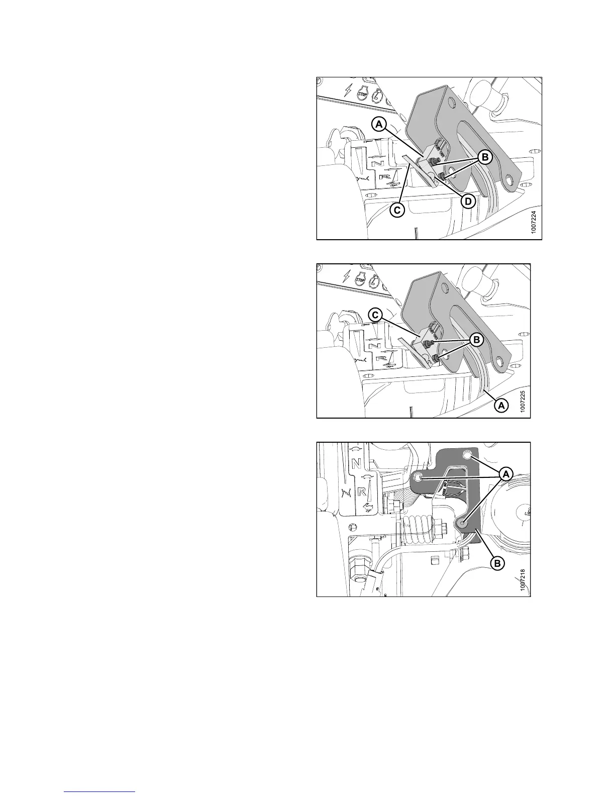
6. Adjust switch (A) a s follows:
a. Loosen nuts (B) and rotate switch on support
sufficiently so that GSL will contact switch lever (C)
and push in the plunger (D).
b. Tighten nuts (B).
Figure 5.31: Interlock S witch
7. If necessary, replace switch as follows:
a. Disconnect wiring harness (A) at connector.
b. Remove nuts and screws (B) and remove the old
switch (C).
c. Install the new switch (C) on the support and
secure with nuts and screws (B).
d. Connect harness (A) to console wiring.
Figure 5.32: Interlock S witch
8. Position the switch support plate (B) inside the console
and secure with rubber nuts (A).
NOTE:
For cla rity, console in the ima ge was made
transparent to show the switch support plate (B).
9. Check operation of the new switch.
Figur
e 5.33: Console (Transparent)
147649 324 Revision A