MAINTENANCE AND S ERVICING
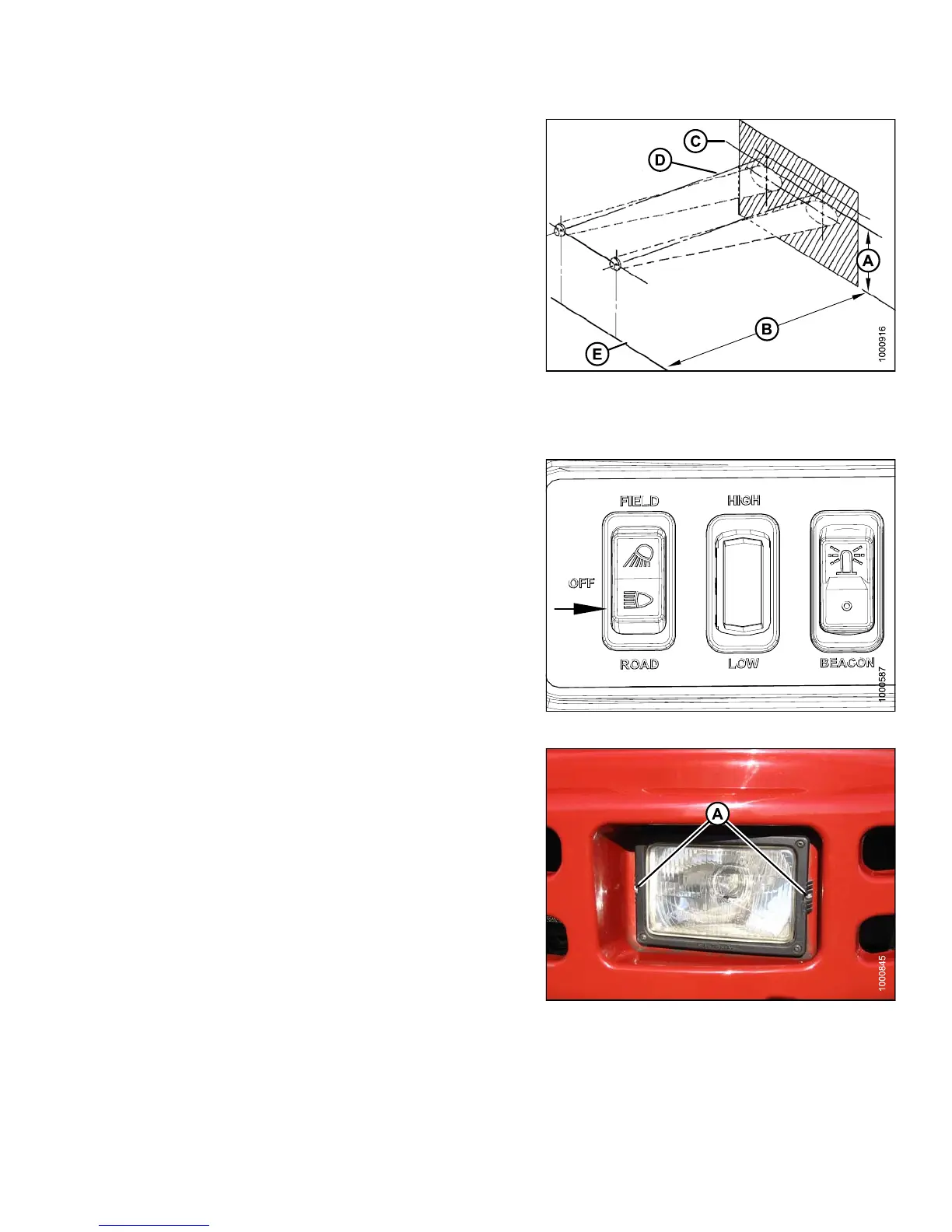
1. Position windrower on level ground in fron t of a vertical
surface in accordance with the illustration.
2. Shut down engine and remove key.
Figure 5.131: Headlight Beam Positioning
A - 49.75 in. (1263 mm) Maximum B - 25 ft (7.5 m)
C - Top Edge o
f Beam
D - Beam Cent
ered on Direction
E - Ground of Tr avel Line
3. Turn on ROAD lights and switch to low-beam.
Figure 5.132: Road Light Switch
4. Align the headlights to the following specifications by
turning adjus ting sc rews (A ).
• Adjustments are for low-beam.
• Light beams laterally centered on the direction of
travel line from the headlights (that is, NOT skewed
left or right).
Figure 5.133: Headlights
147649 377 Revision A