MAINTENANCE AND SERVICING
NOTE:
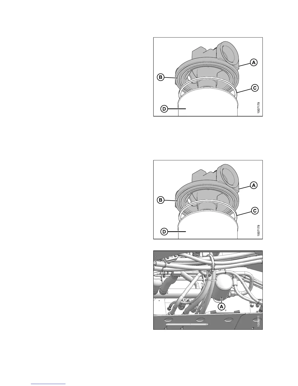
Image showing filter head removed to show
component clarity.
6. Remove gasket
(C) from groove (B) in filt er head (A).
Filter (D) sho
wn for context.
Figure 5.192: Return Filter
Installing Return Filter
NOTE:
For filter s
pecifications, refer to 8.2.4 Filter Part Numbers, page 467.
1. Clean the gaske t groove (B) in the filter head (A).
2. Apply a thin film of clean o il to the filter gasket (C).
3. Install new gasket (C) into the groove (B) in the filter
head (A).
4. Screw the new filter (D) onto the filter head until the
gasket conta cts the filter.
Figure 5.193: Return Filter
5. Tighten filter an additional 3/4 turn by hand.
IMPORTANT:
Do NOT use a filter wrench to install oil filte r.
Overtightening can damage gasket and filter.
6. Check hydraulic fluid levels, refer to Checking and
Filling Hydraulic Oil, page 401. For capacity level, refer
to 8.2.3 L ubricants, Fluids, a nd System Capacities,
page 466.
Figure 5.194: Hydraul ic System
147649 406 Revision A