Installation and Commissioning
GARD 8000 SYS RFL Electronics
November 28, 2017 4-36 973.334.3100
4.6.2.4 VERIFYING CUSTOM DESIGN AUDIO LOGIC
1. From the Home page click on ‘Settings’.
2. Select ‘File Operations’.
3. At File Operations click on ‘Save File to PC’.
4. Click on arrow pointing down and select ‘System Logic PDF (.PDF file)’.
5. Click on ‘Save’ selection and choose to SAVE or OPEN the Logic Design in PDF format.
6. After opening a PDF file the Custom Designed Audio Logic will be displayed under TITLE
located at the bottom right side of the drawing.
7. The Gard8000 downloaded Audio Logic drawing number should be compared with the
Logic number printed on the chassis label located on the mounting brackets.
4.6.2.5 VERIFYING AUDIO SYSTEM PARAMETERS
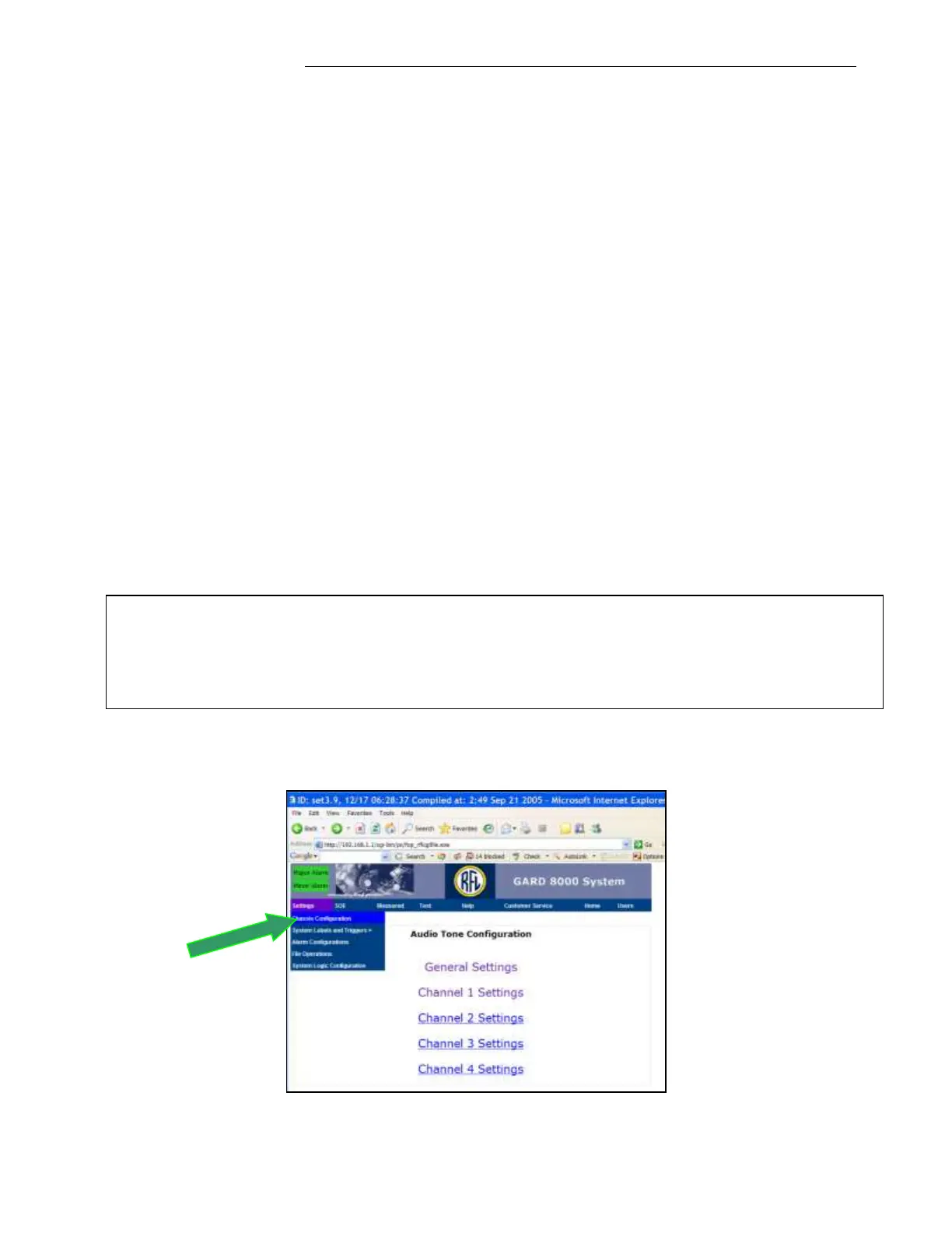
1. From the ‘Home’ page click on ‘Settings’ and select ‘Chassis Configuration’.
2. At ‘Chassis Configuration’ page click on the ‘Audio Tone’ module installed in one of the
Rear Slots.
3. At the ‘Audio Tone Configuration’ page first select the ‘General Settings’ to verify the
overall Audio System Parameters and then verify each of 4 channels operating parameters.
4. Use the Audio Configuration Page to modify the factory programmed parameters for a Local
End testing as well as future End to End normal operation.
5. For Local-End testing insure that the TX/RX Audio Tone levels and Frequencies are the
same.
To display the Option Settings page click on ‘Settings’, select ‘System Logic Configuration’, at
the System Logic Configuration page select ‘Option Settings’
Note
To change a special configuration in Channel 1 from ‘Modem’ to ‘Tripping’ or ‘Tripping’ to
‘Modem’ the programming changes have to be done at two web pages: ‘Audio Tone
Configuration’ and ‘Option Settings’. See below.