RM0091 Reset and clock control (RCC)
Doc ID 018940 Rev 1 115/742
7.4.14 Clock control register 2 (RCC_CR2)
Address: 0x34
Reset value: 0x0000 XX80, where X is undefined.
Access: no wait states, word, half-word and byte access
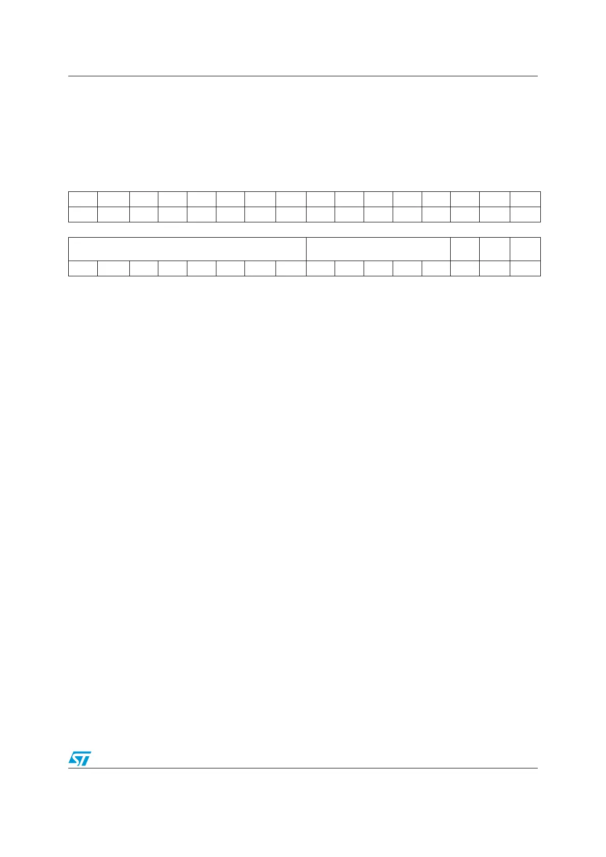
31 30 29 28 27 26 25 24 23 22 21 20 19 18 17 16
Res Res Res Res Res Res Res Res Res Res Res Res Res Res Res Res
15 14 13 12 11 10 9 8 7 6 5 4 3 2 1 0
HSI14CAL[7:0] HSI14TRIM[4:0]
HSI14
DIS
HSI14
RDY
HSI14
ON
r r r r r r r r rwrwrwrwrwrw r rw
Bits 31:16 Reserved, must be kept at reset value.
Bits 15:8 HSI14CAL[7:0]: HSI14 clock calibration
These bits are initialized automatically at startup.
Bits 7:3 HSI14TRIM[4:0]: HSI14 clock trimming
These bits provide an additional user-programmable trimming value that is added to the
HSI14CAL[7:0] bits. It can be programmed to adjust to variations in voltage and temperature
that influence the frequency of the HSI14.
The default value is 16, which, when added to the HSI14CAL value, should trim the HSI to 8
MHz ± 1%. The trimming step (F
hsitrim
) is around 50 kHz between two consecutive HSICAL
steps.
Bit 2 HSI14DIS HSI14 clock request from ADC disable
Set and cleared by software.
When set this bit prevents the ADC interface from enabling the HSI14 oscillator.
0: ADC interface can turn on the HSI14 oscillator
1: ADC interface can not turn on the HSI14 oscillator
Bit 1 HSI14RDY: HSI14 clock ready flag
Set by hardware to indicate that HSI14 oscillator is stable. After the HSI14ON bit is cleared,
HSI14RDY goes low after 6 HSI14 oscillator clock cycles.
0: HSI14 oscillator not ready
1: HSI14 oscillator ready
Bit 0 HSI14ON: HSI14 clock enable
Set and cleared by software.
0: HSI14 oscillator OFF
1: HSI14 oscillator ON