RM0091 Inter-integrated circuit (I
2
C) interface
Doc ID 018940 Rev 1 469/742
● PMBus rev 1.1 standard compatibility
● Independent clock: a choice of independent clock sources allowing the I2C
communication speed to be independent from the PCLK reprogramming
● Wakeup from STOP on address match.
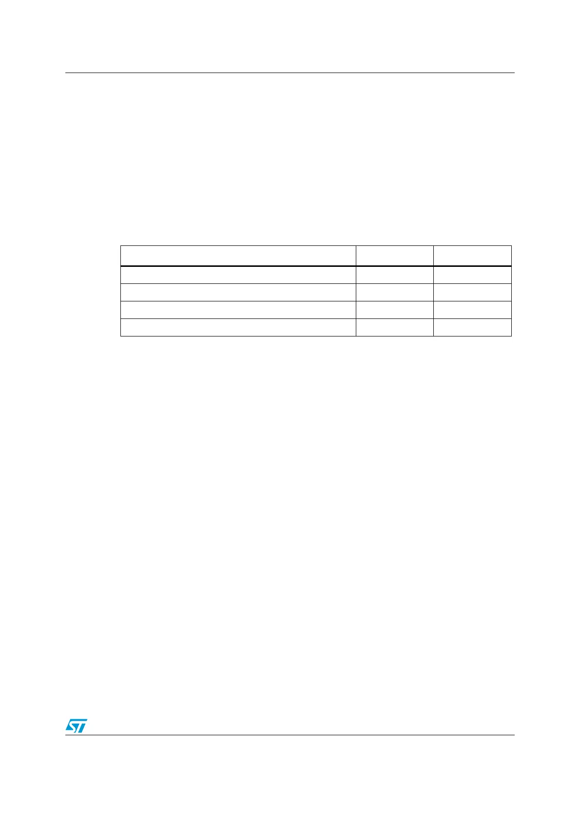
23.3 I2C implementation
This manual describes the full set of features implemented in I2C1. I2C2 supports a smaller
set of features, but is otherwise identical to I2C1. The differences are listed in the following
table.
23.4 I
2
C functional description
In addition to receiving and transmitting data, this interface converts it from serial to parallel
format and vice versa. The interrupts are enabled or disabled by software. The interface is
connected to the I
2
C bus by a data pin (SDA) and by a clock pin (SCL). It can be connected
with a standard (up to 100 kHz), Fast Mode (up to 400 kHz) or Fast Mode Plus (up to 1 MHz)
I
2
C bus.
This interface can also be connected to a SMBus with the data pin (SDA) and clock pin
(SCL).
If SMBus feature is supported: the additional optional SMBus Alert pin (SMBA) is also
available.
Table 62. STM32F05xxx I2C implementation
I2C features
(1)
1. X = supported.
I2C1 I2C2
Independent clock
X
SMBus
X
Wakeup from STOP
X
20 mA output drive for FM+ mode
X