Real-time clock (RTC) RM0091
536/742 Doc ID 018940 Rev 1
24.3 RTC functional description
24.3.1 RTC block diagram
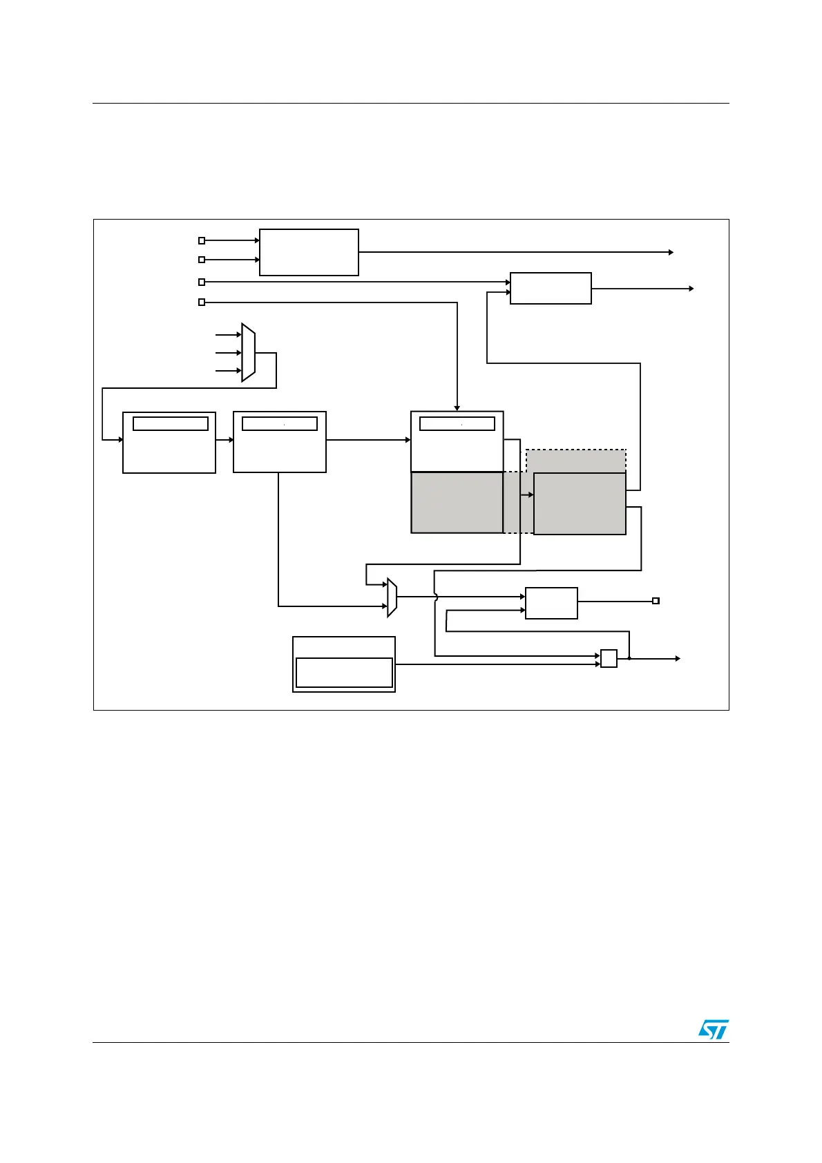
Figure 227. RTC block diagram
The RTC includes:
● One alarm
● Two tamper events
● Five 32-bit backup registers
● Alternate function outputs: RTC_OUT which selects one of the following two outputs:
– RTC_CALIB: 512 Hz or 1Hz clock output (with an LSE frequency of 32.768 kHz).
This output is enabled by setting the COE[23] bit in the RTC_CR register.
– RTC_ALARM: Alarm A. This output is selected by configuring the OSEL[1:0] bits
in the RTC_CR register.
● Alternate function inputs:
– RTC_TS : timestamp event
– RTC_TAMP1: tamper1 event detection
– RTC_TAMP2: tamper2 event detection
– RTC_REFIN: 50 or 60 Hz reference clock input
MS19901V1
RTC_ALARM
512 Hz
RTCCLK
HSE/32
LSE (32.768 Hz)
LSI
Synchronous
15-bit prescaler
(default = 256)
ALRAF
RTC_PRER
TAMPxF
Time stamp
registers
TSF
Output
control
RTC_OUT
RTC_CALR
calibration
1 Hz
RTC_TAMP2
=
Smooth
ck_spre
(default 1 Hz)
RTC_REFIN
RTC_TAMP1
RTC_TS
Asynchronous
7-bit prescaler
(default = 128)
RTC_PRER
Calendar
Shadow registers
RTC_TR,
RTC_DR
Alarm A
RTC_ALRMAR
RTC_ALRMASSR
ck_apre
(default 256 Hz)
RTC_CALIB
Backup registers
and RTC tamper
control registers
Shadow register
RTC_SSR