RM0091 Touch sensing controller (TSC)
Doc ID 018940 Rev 1 685/742
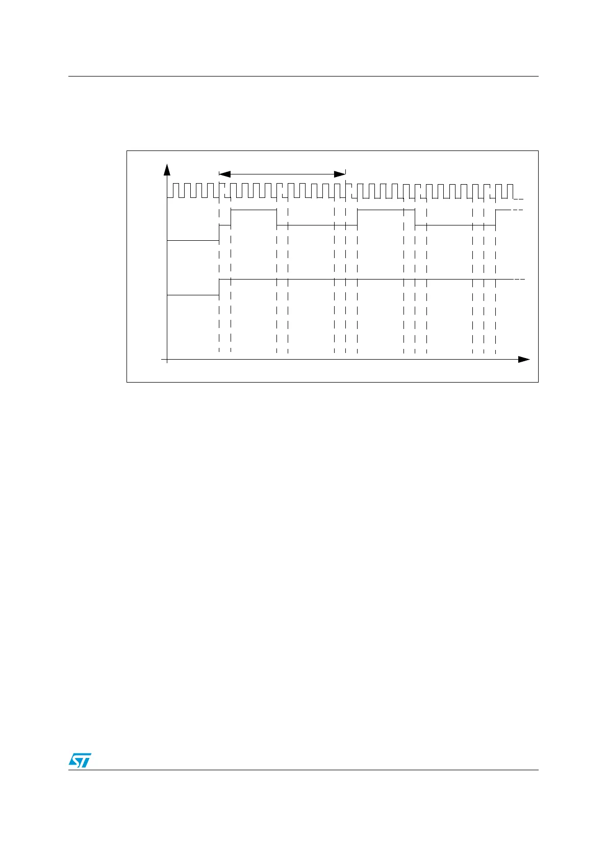
27.3.4 Charge transfer acquisition sequence
An example of a charge transfer acquisition sequence is detailed in Figure 287.
Figure 287. Charge transfer acquisition sequence
For higher flexibility, the charge transfer frequency is fully configurable. Both the pulse high
state (charge of C
X
) and the pulse low state (transfer of charge from C
X
to C
S
) duration can
be defined using the CTPH[3:0] and CTPL[3:0] bits in the TSC_CR register. The standard
range for the pulse high and low states duration is 500 ns to 2 µs. To ensure a correct
measurement of the electrode capacitance, the pulse high state duration must be set to
ensure that C
X
is always fully charged.
A dead time where both the sampling capacitor I/O and the channel I/O are in input floating
state is inserted between the pulse high and low states to ensure an optimum charge
transfer acquisition sequence. This state duration is 2 periods of f
HCLK
.
At the end of the pulse high state and if the spread spectrum feature is enabled, a variable
number of periods of f
SSCLK
are added.
The reading of the sampling capacitor I/O, to determine if the voltage across C
S
has
reached the given threshold, is performed at the end of the pulse low state and its duration
is one period of f
HCLK
.
charge transfer frequency
Dead time state
Pulse low state
Spread Spectrum state
(charge transfer
C
S
reading state
C
X
HiZ
1
0
C
S
HiZ
1
0
State
CLK_AHB
t
Discharge
C
X
and C
S
Pulse high state
(charge of C
X
)
from C
X
to C
S
)
Dead time state
Dead time state
Dead time state
C
S
reading state
Dead time state