RM0091 Universal synchronous asynchronous receiver transmitter (USART)
Doc ID 018940 Rev 1 599/742
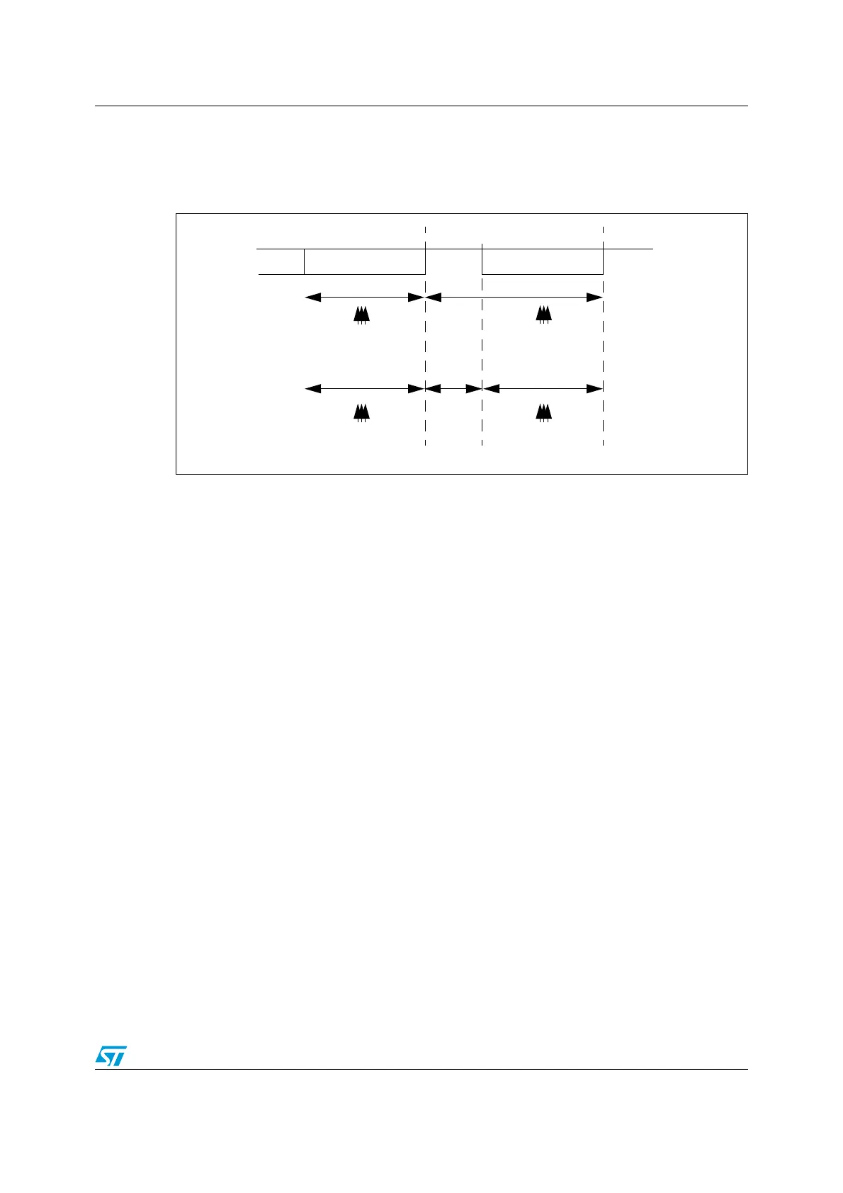
Figure 244 details how the NACK signal is sampled by the USART. In this example the
USART is transmitting data and is configured with 1.5 stop bits. The receiver part of the
USART is enabled in order to check the integrity of the data and the NACK signal.
Figure 244. Parity error detection using the 1.5 stop bits
The USART can provide a clock to the Smartcard through the SCLK output. In Smartcard
mode, SCLK is not associated to the communication but is simply derived from the internal
peripheral input clock through a 5-bit prescaler. The division ratio is configured in the
prescaler register USART_GTPR. SCLK frequency can be programmed from f
CK
/2 to
f
CK
/62, where f
CK
is the peripheral input clock.
Block mode (T=1)
In T=1 (block) mode, the parity error transmission is deactivated, by clearing the NACK bit in
the UART_CR3 register.
When requesting a read from the Smartcard, in block mode, the software must program the
RTOR register to the BWT (block wait time) - 11 value. If no answer is received from the card
before the expiration of this period, a timeout interrupt will be generated. If the first character
is received before the expiration of the period, it is signaled by the RXNE interrupt.
Note: The RXNE interrupt must be enabled even when using the USART in DMA mode to read
from the Smartcard in block mode. In parallel, the DMA must be enabled only after the first
received byte.
After the reception of the first character (RXNE interrupt), the RTO register must be
programmed to the CWT (character wait time) - 11 value, in order to allow the automatic
check of the maximum wait time between two consecutive characters. This time is
expressed in baudtime units. If the Smartcard doesn’t send a new character in less than the
CWT period after the end of the previous character, the USART signals this to the software
through the RTOF flag and interrupt (when RTOIE bit is set).
Note: The RTO counter starts counting from the end of the first stop bit of the last character in
cases STOP = 00, 10. In case of STOP = 11, the RTO counter starts counting 1 bit time after
the beginning of the STOP bit. As in the Smartcard protocol definition, the BWT/CWT values
are defined from the beginning (start bit) of the last character. The RTO register must be
programmed to BWT -11 or CWT -11, respectively, taking into account the length of the last
character itself.
1 bit time 1.5 bit time
0.5 bit time 1 bit time
sampling at
8th, 9th, 10th
sampling at
8th, 9th, 10th
sampling at
8th, 9th, 10th
sampling at
16th, 17th, 18th
Bit 7 Parity Bit 1.5 Stop Bit